4 OPERATION/PROGRAMMING
4.1 Control panel
Using the control panel, operating modes can be selected and the robot can be switched to
MOTOR ON or MOTOR OFF. Lamps inside the buttons indicate status and any
malfunction. The control panel also includes one of the emergency stop buttons.
Lockable switch for selection of operation mode:
AUTO
MANUAL REDUCED SPEED <250 mm/8
MANUAL FULL SPEED
100 %
Program run at maximum speed.
Program edit and joystick run is
not allowed.
Programming and program
running with maximum
speed 250 mm/s.
Test run at maximum speed.
H]
MOTOR ON mode pushbutton.
MOTOR ON mode is indicated by light inside the button. Indication "External axis not synchronized"
by means of a twinkling MOTOR OFF light. The robot motors are activated in the MOTOR ON mode.
MOTOR OFF mode pushbutton.
MOTOR OFF mode is indicated by light inside the button. Indication "ERROR" by means of a
twinkling MOTOR OFF light.
The system is activated in the MOTOR OFF mode but not the robot motors.
Emergency stop button.
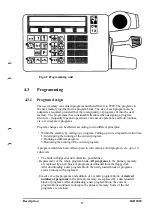
Fig4.1 Control panel
Description
1KB 2000
15
Summary of Contents for IRB 2000
Page 8: ...Description 1KB 2000 ...
Page 10: ...Description 1KB 2000 ...
Page 12: ...Description 1KB 2000 6 ...
Page 20: ...Description 1KB 2000 14 ...
Page 32: ...Description 1KB 2000 26 ...
Page 40: ...5 3 2 Dimensional drawings Description 34 1KB 2000 ...
Page 41: ..._200 _D D_ Description 35 1KB 2000 ...
Page 44: ...Description 1KB 2000 38 ...
Page 64: ...Description 1KB 2000 58 ...
Page 77: ...Safety 1KB 2000 IBB 3000 12 1KB 3200 1KB 6000 ...
Page 80: ...Installation H B 2000 ...
Page 82: ...Installation 1KB 2000 ...
Page 91: ...Installation 1KB 2000 12 ...
Page 95: ...Installation 1KB 2000 16 ...
Page 110: ...INSTALLATION S3 0 4 ...
Page 112: ...INSTALLATION S3 1 2 ...
Page 160: ...INSTALLATION 3 46 ...
Page 234: ...INSTALLATION 5 70 ...
Page 262: ...INSTALLATION S3 7 6 ...


