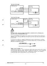
In24V suppl
Control
I
system
MON
OVI/O
+24 V I/O
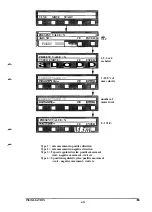
EXT MON A
EXT MON B
External
drive unit
n
Ex24V supp
Control system
MON
| EXT MON A
| - ^ " EXT MON B
External
+24 V
External
drive unit
n
>£**
Note:
From the safety aspect it is important that the external motor is without power
when the robot is in MOTOR OFF mode.
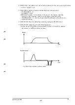
The signal EXT BRAKE ON should be used to block the speed controller of the external axis
(BLOCK signal), so that any offset does not integrate up to the current limit when the brakes
are activated.
To prevent an external axis equipped with brake from moving when the brake is operated
(applicable to axes affected by gravitation), an extra time-delay may be created between EXT
BRAKE ON and BLOCK as follows.
EXT BRAKE ON
Rl OOK
VREF (7-12), 0 V VREF (7-12)
Analog reference signal,-10 - +10 V, for the speed reference from control system to the external
drive unit System parameters define which max. voltage in the range -9.4 - +9.4 V corresponds
to the defined max. speed in the range -3000 - +3000 rpm. See section 5.2.4.13 relating to
system parameters for the speed reference to an external drive unit.
INSTALLATION
S3
6:9
Summary of Contents for IRB 2000
Page 8: ...Description 1KB 2000 ...
Page 10: ...Description 1KB 2000 ...
Page 12: ...Description 1KB 2000 6 ...
Page 20: ...Description 1KB 2000 14 ...
Page 32: ...Description 1KB 2000 26 ...
Page 40: ...5 3 2 Dimensional drawings Description 34 1KB 2000 ...
Page 41: ..._200 _D D_ Description 35 1KB 2000 ...
Page 44: ...Description 1KB 2000 38 ...
Page 64: ...Description 1KB 2000 58 ...
Page 77: ...Safety 1KB 2000 IBB 3000 12 1KB 3200 1KB 6000 ...
Page 80: ...Installation H B 2000 ...
Page 82: ...Installation 1KB 2000 ...
Page 91: ...Installation 1KB 2000 12 ...
Page 95: ...Installation 1KB 2000 16 ...
Page 110: ...INSTALLATION S3 0 4 ...
Page 112: ...INSTALLATION S3 1 2 ...
Page 160: ...INSTALLATION 3 46 ...
Page 234: ...INSTALLATION 5 70 ...
Page 262: ...INSTALLATION S3 7 6 ...


