A Tool Centre Line (TCL) can be created by defining a base point (BASEP)
together with the TCP in the wrist-oriented coordinate system. The TCL then
constitutes the x-axis in a tool-oriented coordinate system. The TCL is
mainly based on the orientation of a tool or a gripper relative to the turn plate
and enables a gripper or a tool to be moved parallel to its own configuration.
• Fixed TCP (see Programming manual S3 art. no. 3HAB 0002-2 ).
The function makes the manual operation of the robot, when the robot holds
the workpiece and the tool is fixed mounted in the room. At reorientation of the
workpiece the movement is done in relation to the fixed TCP-point, un-
depended of the position of the robot.
Automatic operation
When the system is operating automatically, the robot will move from its current
position to a programmed position.
Each position is stored in the memory as the position of the TCP together with
either:
• the wrist orientation (wrist-oriented coordinate system) or,
• the tool orientation (tool-oriented coordinate system).
Three different types of automatic running are available:
• Robot coordinate movement.
All axes are individually moved at constant speed towards the programmed
position. All axes reach their respective end position simultaneously.
• Straight-line movement.
The TCP/TCL is moved straight and at constant speed towards a programmed
position. Any reorientation of the wrist or the TCL will be performed
continuously during the movement.
• Modified straight-line movement.
Straight-line movement of TCP but "Robot coordinate" movement of wrist axes.
The system speed is determined by:
• an absolute speed in mm/s or inches/s for the current section of the program;
• a percentage of the absolute speed for each movement instruction;
• an adjustment factor as a percentage of the speed determined by the above
points.
Description 1KB 2000
19
Summary of Contents for IRB 2000
Page 8: ...Description 1KB 2000 ...
Page 10: ...Description 1KB 2000 ...
Page 12: ...Description 1KB 2000 6 ...
Page 20: ...Description 1KB 2000 14 ...
Page 32: ...Description 1KB 2000 26 ...
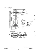
Page 40: ...5 3 2 Dimensional drawings Description 34 1KB 2000 ...
Page 41: ..._200 _D D_ Description 35 1KB 2000 ...
Page 44: ...Description 1KB 2000 38 ...
Page 64: ...Description 1KB 2000 58 ...
Page 77: ...Safety 1KB 2000 IBB 3000 12 1KB 3200 1KB 6000 ...
Page 80: ...Installation H B 2000 ...
Page 82: ...Installation 1KB 2000 ...
Page 91: ...Installation 1KB 2000 12 ...
Page 95: ...Installation 1KB 2000 16 ...
Page 110: ...INSTALLATION S3 0 4 ...
Page 112: ...INSTALLATION S3 1 2 ...
Page 160: ...INSTALLATION 3 46 ...
Page 234: ...INSTALLATION 5 70 ...
Page 262: ...INSTALLATION S3 7 6 ...


