37x
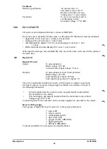
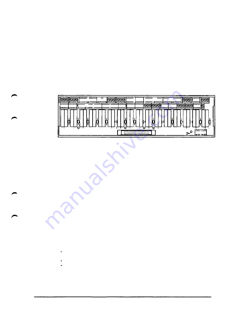
Relay units (6)
Terminal unit with 16 relay outputs.
This option can be selected alone or in combination with 34x or 36x. If the relay units are
combined with 34x or 36, they are placed after the other terminal units.
In addition, the relay unit is equipped with 10 + 10 terminals for 24 V DC supply and
8 + 8 terminal for optional supply. Max. load per terminal group 6.3 A.
Data relay unit
16 relays with one change-over contact
Maximum current
Rated voltage
outputs
4 A per relay
250 VAC
Inputs according to option 20x. T he inputs are not seperated by relays.
I OCXS ® s ®
Ho~i
GXSXsllsHSKS
bod
9G>®ta®S>j®®®
Ho nHo~i
®C9®|CXX
Ho~i
1
T
c
9®CXs
SKSXSJ
SKSXS
5 5 5
®Q®
Ho~i
J®Q®|b®6
L
r
S ssdlos®
3®S
1
r
o H
QSXS
o
L
r
H o
-c
i
r
o
SXSNS
SXSKS
o
SOJSXS
)
o
38x
Fig 6.13 Relay units
Connections from connectors
External connections via screw terminal board
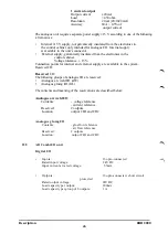
All signals are connected to 64-pole contact units as per DIN 43652 with pin arrangement
as per insulation manual S3.
39x As in 38x above, but where the user establishes the pin arrangement by filling in the wiring
table 3HAB 2123-7 in conjunction with his order.
400 ADDITIONAL EQUIPMENT
The robot system can be supplied with any desired combination of additional equipment
as follows:
401 Program print-out
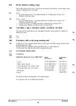
The print-out function makes it possible to connect a printer to the robot system for
printing:
Individual programs including TCP positions. The operator is able to
request 5 print-outs through a signal command.
The contents of the fault message buffer.
System parameters.
The robot communicates with the printer through asynchronous series transmission via an
RS 232 signal interface. This printer must be fitted with an internal buffer memory.
The connections for the printer are situated on the front of the control system,
where there is a 25-pole contact (D sub).
Description
IRB2000
51
Summary of Contents for IRB 2000
Page 8: ...Description 1KB 2000 ...
Page 10: ...Description 1KB 2000 ...
Page 12: ...Description 1KB 2000 6 ...
Page 20: ...Description 1KB 2000 14 ...
Page 32: ...Description 1KB 2000 26 ...
Page 40: ...5 3 2 Dimensional drawings Description 34 1KB 2000 ...
Page 41: ..._200 _D D_ Description 35 1KB 2000 ...
Page 44: ...Description 1KB 2000 38 ...
Page 64: ...Description 1KB 2000 58 ...
Page 77: ...Safety 1KB 2000 IBB 3000 12 1KB 3200 1KB 6000 ...
Page 80: ...Installation H B 2000 ...
Page 82: ...Installation 1KB 2000 ...
Page 91: ...Installation 1KB 2000 12 ...
Page 95: ...Installation 1KB 2000 16 ...
Page 110: ...INSTALLATION S3 0 4 ...
Page 112: ...INSTALLATION S3 1 2 ...
Page 160: ...INSTALLATION 3 46 ...
Page 234: ...INSTALLATION 5 70 ...
Page 262: ...INSTALLATION S3 7 6 ...


