2 Installation and commissioning
2.3.2. Manually releasing the brakes
45
3HAC022031-001 Revision: C
©
Co
py
rig
h
t 200
4-
200
8 ABB. All righ
ts reser
v
ed.
2.3.2. Manually releasing the brakes
General
The holding brakes of each axis’ motor are of an electromechanical type and are released
when voltage is applied. This section details how to release the brakes, using the internal
brake release unit, in order to enable the axes to move manually.
The brake of each motor can also be released by connecting an external voltage supply
directly on the motor connector, see the circuit diagram or the repair procedures for each
motor (section
).
Releasing the brakes using the brake release unit
The procedure below details how to release the holding brakes using the internal brake release
unit.
Action
Note/Illustration
1.
DANGER!
When releasing the holding brakes, the robot
axes may move very quickly and sometimes in
unexpected ways! Make sure no personnel is
near the robot arm!
2. If the robot is not connected to the controller,
power must be supplied to the connector
R1.MP.
Detailed in section
.
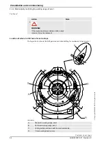
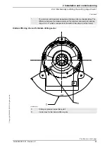
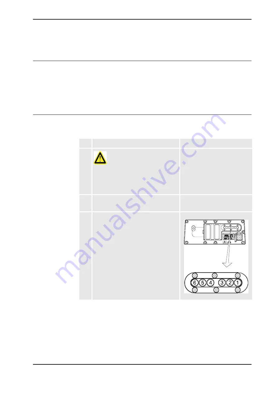
3. The internal brake release unit is located at the
base of the robot and equipped with buttons
for controlling the holding brakes for each axis
separately. The buttons are numbered
according to the numbers of the axes.
To release the brake on a particular robot axis,
push the corresponding button on the internal
brake release panel and keep it depressed.
The brake will function again as soon as the
button is released.
xx0600002697
Continues on next page
Summary of Contents for IRB 2400/10
Page 1: ...Product manual Articulated robot IRB 2400 L IRB 2400 10 IRB 2400 16 M2000 M2000A M2004 ...
Page 2: ......
Page 8: ...Table of Contents 6 3HAC022031 001 Revision C Copyright 2004 2008 ABB All rights reserved ...
Page 191: ......
Page 192: ......
Page 193: ......
Page 194: ......
Page 195: ......
Page 198: ......
Page 199: ......
Page 202: ......
Page 203: ......
Page 205: ......
Page 226: ......


