2 Installation and commissioning
2.3.3. Orienting and securing the robot
47
3HAC022031-001 Revision: C
©
Co
py
rig
h
t 200
4-
200
8 ABB. All righ
ts reser
v
ed.
2.3.3. Orienting and securing the robot
General
This section details how to orient and secure the robot to the foundation in order to safely run
the robot. The requirements for the foundations are shown in the tables and figures below.
Bolting requirements
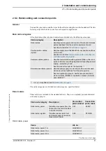
When bolting a base plate or the base to a concrete floor, follow the general instructions for
expansion-shell bolts. The screw joint must be able to withstand the stress loads defined in
Loads on foundation on page 40
NOTE!
When the robot is to be mounted in a tilted or a suspended position, the guide sleeves must
be used to secure the bolted joint.
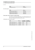
Attachment screws
The table below specifies the type of securing screws and washers to be used for securing the
robot to the base plate/foundation.
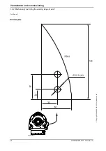
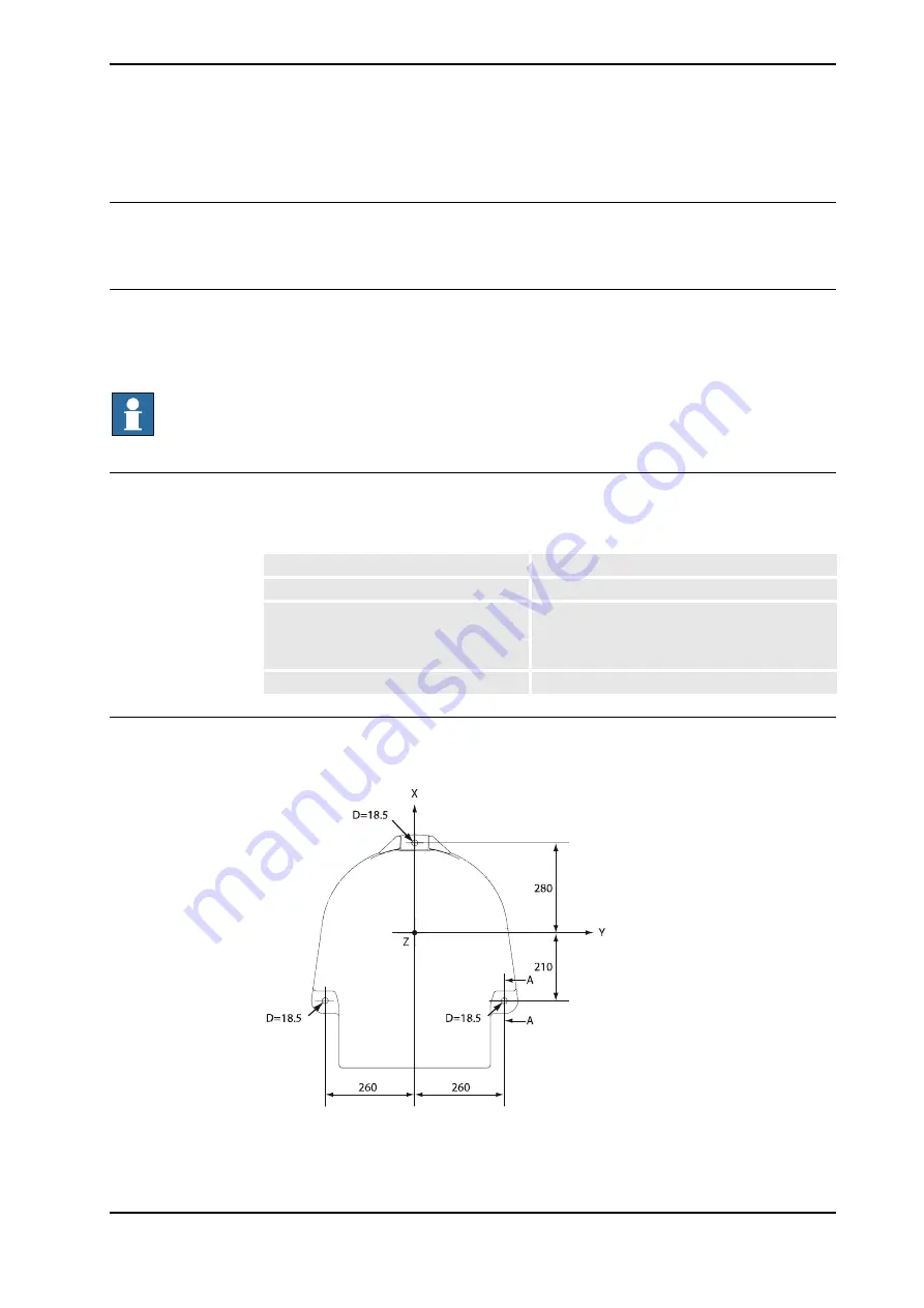
Hole configuration
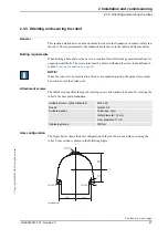
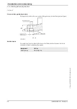
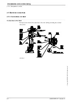
The figure below shows the hole configuration of the robot base, used when securing the
robot. Cross section is shown in the following figure.
xx0200000181
Suitable screws, lightly lubricated:
M16 x 50
Quality
Quality 8.8
Suitable washer:
Thickness: 3 mm
Outer diameter: 30 mm
Inner diameter: 17 mm
Tightening torque:
190 Nm
Continues on next page
Summary of Contents for IRB 2400/L
Page 1: ...Product manual Articulated robot IRB 2400 L IRB 2400 10 IRB 2400 16 M2000 M2000A M2004 ...
Page 2: ......
Page 8: ...Table of Contents 6 3HAC022031 001 Revision C Copyright 2004 2008 ABB All rights reserved ...
Page 191: ......
Page 192: ......
Page 193: ......
Page 194: ......
Page 195: ......
Page 198: ......
Page 199: ......
Page 202: ......
Page 203: ......
Page 205: ......
Page 226: ......

