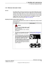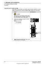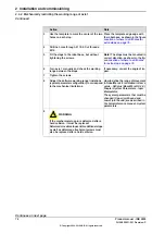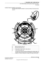
Supplying power to connector R1.MP
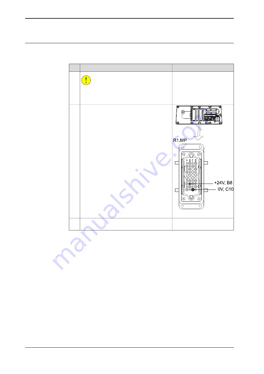
If the robot is not connected to the controller, power must be supplied to connector
R1.MP in the robot base in order to enable the brake release unit on the robot.
Note/Illustration
Action
CAUTION
Be careful not to interchange the 24 VDC and 0V
pins! If they are mixed up, damage can be caused
to a resistor diode and to the system board.
1
xx0200000167
Connect an external power supply to connector
R1.MP, at the robot base.
Supply:
•
+24 V on pin B8
•
0 V on pin C10
2
Release the brakes with the brake release unit as
detailed in the previous procedure.
3
60
Product manual - IRB 2400
3HAC022031-001 Revision: P
© Copyright 2004-2018 ABB. All rights reserved.
2 Installation and commissioning
2.3.2 Manually releasing the brakes
Continued
Summary of Contents for IRB 2400 Series
Page 1: ...ROBOTICS Product manual IRB 2400 ...
Page 8: ...This page is intentionally left blank ...
Page 18: ...This page is intentionally left blank ...
Page 204: ...This page is intentionally left blank ...
Page 220: ...This page is intentionally left blank ...
Page 232: ...This page is intentionally left blank ...
Page 234: ...This page is intentionally left blank ...
Page 240: ......
Page 241: ......


