background image

1.10 Customer connections

1.10.1 Customer connection on robot

Location of customer connection

For the connection of extra equipment to the robot, cables and air hose are
integrated into the robot´s cabling, and there can be two UTOW71210SH06 and
one UTOW71626SH06 connector on the front part of the upper arm.

Note

The maximum leakage current for attached equipment must not exceed 10mA.

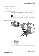
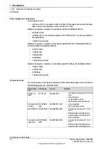
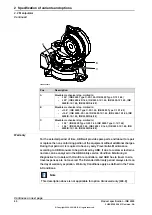
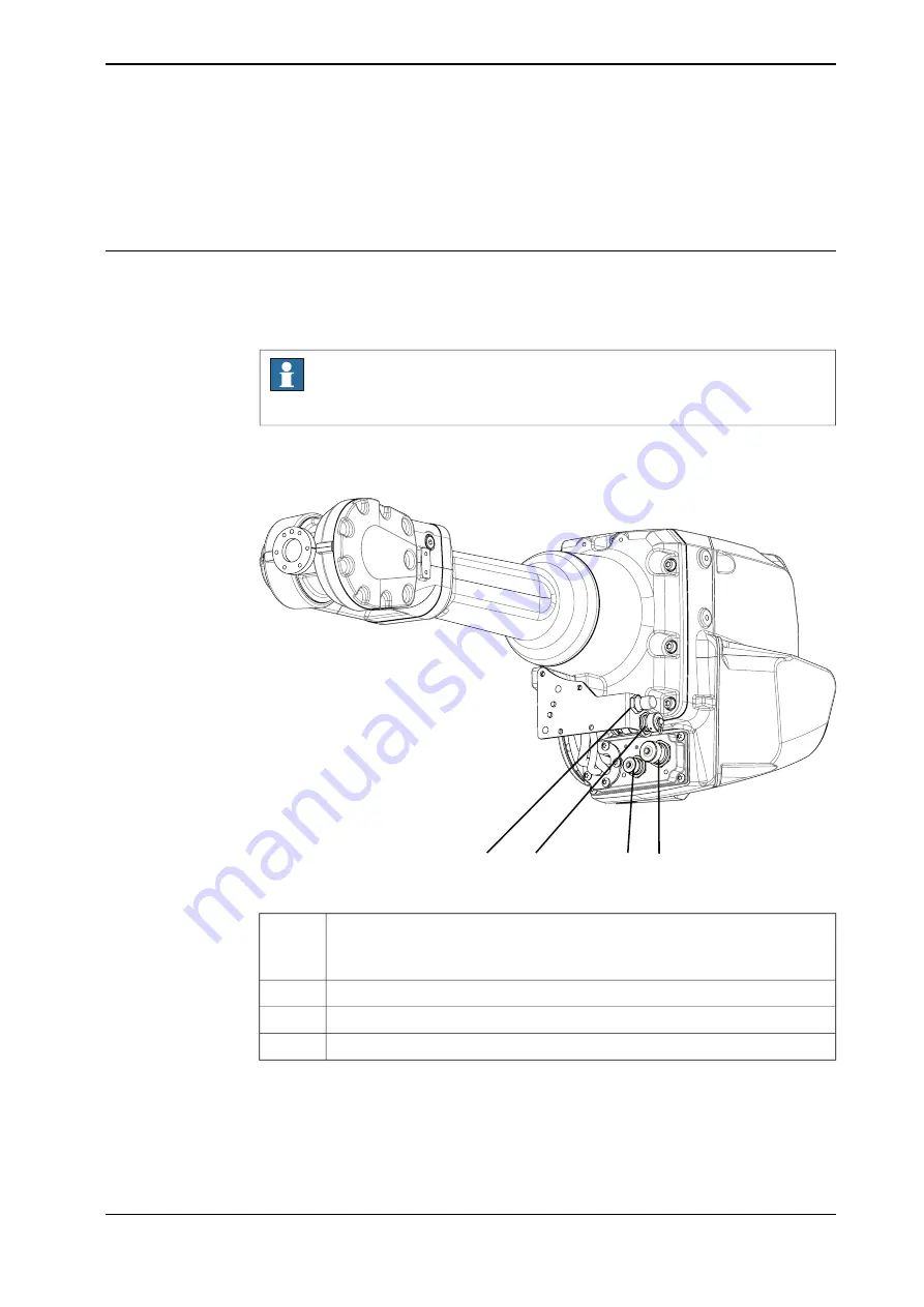
The customer connections are located on the robot as shown in the figure.

Customer connections on upper arm

A

B

C

D

xx2000001657

R2.PROC1

A

Air M16x1.5
(24° cone sealing)

R2.ETHERNET

B

R2.CP or R2.CBUS

C

R2.CS or R2.CP/CS

D

Continues on next page

Product specification - IRB 2600

69

3HAC035959-001 Revision: AA

© Copyright 2009-2021 ABB. All rights reserved.

1 Description

1.10.1 Customer connection on robot

Summary of Contents for IRB 2600

Page 1: ...ROBOTICS Product specification IRB 2600 ...

Page 2: ...Trace back information Workspace 21C version a3 Checked in 2021 09 23 Skribenta version 5 4 005 ...

Page 3: ...2600 12 1 65 IRB 2600 12 1 85 IRB 2600 20 1 65 type C IRB 2600 12 1 65 type C IRB 2600ID 15 1 85 IRB 2600ID 8 2 0 Document ID 3HAC035959 001 Revision AA Copyright 2009 2021 ABB All rights reserved Specifications subject to change without notice ...

Page 4: ...ty by ABB for losses damage to persons or property fitness for a specific purpose or the like In no event shall ABB be liable for incidental or consequential damages arising from use of this manual and products described herein This manual and parts thereof must not be reproduced or copied without ABB s written permission Keep for future reference Additional copies of this manual may be obtained f...

Page 5: ... 5 Maximum TCP acceleration 52 1 6 Mounting equipment 52 1 6 1 Information about mounting equipment 61 1 7 Maintenance and Troubleshooting 61 1 7 1 Introduction to Maintenance and Troubleshooting 62 1 8 Robot Motion 62 1 8 1 Introduction to Robot Motion 65 1 8 2 Performance according to ISO 9283 66 1 8 3 Velocity 67 1 8 4 Robot stopping distances and times 68 1 9 Cooling fan for axis 1 2 motor 69 ...

Page 6: ...This page is intentionally left blank ...

Page 7: ...rder and Customer Service personnel References Document ID Reference 3HAC047400 001 Product specification Controller IRC5 IRC5 with main computer DSQC1000 3HAC050945 001 Product specification Controller software IRC5 IRC5 with main computer DSQC1000 and RobotWare 5 6x 3HAC050945 001 Product specification Controller software IRC5 IRC5 with main computer DSQC1000 and RobotWare 6 3HAC035504 001 Produ...

Page 8: ... manipulator on page 24 Updated drawing for tool flange Information about mounting equipment on page 52 Q Published in release R17 2 The following updates are done in this revision Tool flange drawings changed Updated list of applicable standards TCP acceleration information added R Published in release R18 2 The following updates are done in this revision Manipulator axes rotation direction figur...

Page 9: ...g updates are done in this revision Modified in Customer connections section X Published in release 20D The following updates are done in this revision Warranty section updated Y Published in release 21A The following updates are done in this revision Added information in section Information about mounting equipment on page 52 Z Published in release 21C The following updates are done in this revis...

Page 10: ...This page is intentionally left blank ...

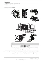
Page 11: ...duct specification Controller software IRC5 Protection type Foundry Plus 2 Robots with the option Foundry Plus 2 are designed for harsh environments where the robot is exposed to sprays of coolants lubricants and metal spits that are typical for die casting applications or other similar applications Typical applications are spraying insertion and part extraction of die casting machines handling in...

Page 12: ... proven connectors Nickel coated tool flange Rust preventives on screws washers and unpainted machined surfaces Extended service and maintenance program The Foundry Plus 2 robot can be cleaned with appropriate washing equipment according to the robot product manual Appropriate cleaning and maintenance is required to maintain the protection for example can rust preventive be washed off with wrong c...

Page 13: ...tion Pos Description Pos Axis 2 B Axis 1 A Axis 4 D Axis 3 C Axis 6 F Axis 5 E Product specification IRB 2600 13 3HAC035959 001 Revision AA Copyright 2009 2021 ABB All rights reserved 1 Description 1 1 1 Introduction to Structure Continued ...

Page 14: ...20 1 65 IRB2600 12 1 65 IRB2600 12 1 85 IRB2600ID 15 1 85 IRB2600ID 8 20 72 dB A Leq acc to Machinery directive 2006 42 EG 69 dB A Leq acc to Machinery directive 2006 42 EG The sound pressure level outside the working space Airborn noise level Power consumption at max load IRB 2600 Type of Movement ID 8 2 00 ID 15 1 85 12 1 85 12 1 65 20 1 65 0 86 kW 0 86 kW 0 92 kW 0 953 kW 0 941 kW ISO Cube Max ...

Page 15: ...012 Description Pos 630 mm A Continues on next page Product specification IRB 2600 15 3HAC035959 001 Revision AA Copyright 2009 2021 ABB All rights reserved 1 Description 1 1 2 Different robot versions Continued ...

Page 16: ...scription Pos R 337 Minimum turning radius of axis 1 A R 98 Minimum turning radius of axis 4 B IRB 2600ID 281 mm C Other types than Type A IRB 2600ID 276 mm Continues on next page 16 Product specification IRB 2600 3HAC035959 001 Revision AA Copyright 2009 2021 ABB All rights reserved 1 Description 1 1 2 Different robot versions Continued ...

Page 17: ...cription Pos For all other dimensions see IRB 2600 20 12 1 65 B Continues on next page Product specification IRB 2600 17 3HAC035959 001 Revision AA Copyright 2009 2021 ABB All rights reserved 1 Description 1 1 2 Different robot versions Continued ...

Page 18: ...For dimensions see IRB 2600 X 1 85 A R 172 Minimum turning radius for axis 4 B Continues on next page 18 Product specification IRB 2600 3HAC035959 001 Revision AA Copyright 2009 2021 ABB All rights reserved 1 Description 1 1 2 Different robot versions Continued ...

Page 19: ...iption Pos For dimensions see IRB 2600 X 1 85 A R 172 Minimum turning radius for axis 4 B Product specification IRB 2600 19 3HAC035959 001 Revision AA Copyright 2009 2021 ABB All rights reserved 1 Description 1 1 2 Different robot versions Continued ...

Page 20: ...0 Safety of machinery Safety related parts of control systems Part 1 General principles for design ISO 13849 1 2006 Safety of machinery Emergency stop Principles for design ISO 13850 Safety of machinery Electrical equipment of machines Part 1 General requirements IEC 60204 1 2005 Safety of machinery Functional safety of safety related elec trical electronic and programmable electronic control syst...

Page 21: ... 2012i Arc welding equipment Part 10 EMC requirements IEC 60974 10 2014i Classification of air cleanliness ISO 14644 1 2015ii Degrees of protection provided by enclosures IP code IEC 60529 1989 A2 2013 i Only valid for arc welding robots Replaces IEC 61000 6 4 for arc welding robots ii Only robots with protection Clean Room Product specification IRB 2600 21 3HAC035959 001 Revision AA Copyright 200...

Page 22: ...Motion on page 62 for limitations Extra loads Extra loads which are included in the load diagrams can be mounted on the upper arm An extra load of 35 kg can also be mounted on the frame of axis 1 See Information about mounting equipment on page 52 Working range limitations The working range of axis 1 can be limited by mechanical stops as option The option Electronic Position Switches can also be u...

Page 23: ... controller 25 C 13 F to 55 C 131 F Standard Complete robot during trans portation and storage up to 70 C 158 F Standard For short periods not exceed ing 24 hours i At low environmental temperature 10o C is as with any other machine a warm up phase is recommended to be run with the robot Otherwise there is a risk that the robot stops or run with lower performance due to temperature dependent oil a...

Page 24: ...e z 7800 Nm i 3440 Nm i Torque xy 3050 Nm i 1110 Nm i Torque z i Only valid for IRB 2600 20 1 65 IRB 2600 12 1 65 IRB 2600 12 1 85 IRB 2600ID 15 1 85 IRB 2600ID 8 2 0 IRB 2600 Type C 20 1 65 IRB 2600 Type C 12 1 65 is not available for suspended installation Note The suspended mounting required option 224 2 Inverted mounting See Expansion container for inverted mounting of the manipulator on page ...

Page 25: ...rque z Tz A Note regarding Mxy and Fxy The bending torque Mxy can occur in any direction in the XY plane of the base coordinate system The same applies to the transverse force Fxy Continues on next page Product specification IRB 2600 25 3HAC035959 001 Revision AA Copyright 2009 2021 ABB All rights reserved 1 Description 1 3 3 Mounting the manipulator Continued ...

Page 26: ... 3 pcs M16 x 70 80 installation on foundation or base plate using guiding sleeves 17 x 30 x 3 Washers 3 pcs Quality 8 8 Quality 200 Nm Tightening torque Note For best AbsAcc performance use the guide holes according to the preceeding figure Mounting surface and bushings Note Only the three outer holes are used to secure the robot Continues on next page 26 Product specification IRB 2600 3HAC035959 ...

Page 27: ...015 J8 Ø35 1 1 6 2 5 25 2x 1x45º Ø22 0 025 0 050 f7 Ø 35 A A C D E F Ø Ø M 16 x 30 Min xx0900000392 Description Pos 3x common zone C Position of the front of the robot E 1xM16 depth 30 minimum F Guide sleeves 2 pcs G Product specification IRB 2600 27 3HAC035959 001 Revision AA Copyright 2009 2021 ABB All rights reserved 1 Description 1 3 3 Mounting the manipulator Continued ...

Page 28: ... inverted robots IRB 2600 20 1 65 IRB 2600 12 1 65 IRB 2600 12 1 85 IRB 2600ID 15 1 85 IRB 2600ID 8 2 0 to make sure that the amount of oil in gearbox axis 1 covers all important parts Robots ordered as suspended robots have the expansion container installed on delivery Expansion container When the robot is fitted in a inverted mounting position an expansion container for oil must be fitted on gea...

Page 29: ...ing D220x5 E Attachment screw M5x20 quality 8 8 A2F and washer 2 2 pcs F O ring D1 9 5 D2 1 6 G Oil plug to be removed H Product specification IRB 2600 29 3HAC035959 001 Revision AA Copyright 2009 2021 ABB All rights reserved 1 Description 1 3 4 Expansion container for inverted mounting of the manipulator Continued ...

Page 30: ...re Based on standard calibration and besides positioning the robot at synchronization posi tion the Absolute accuracy calibration also compensates for Mechanical tolerances in the robot structure Deflection due to load Absolute accuracy calibration focuses on pos itioning accuracy in the Cartesian coordinate system for the robot Absolute accuracy calibration option al Absolute accuracy calibration...

Page 31: ... describes the method and the different routines further Axis Calibration method Axis Calibration is a standard calibration method for calibration of IRB 2600 and is the most accurate method for the standard calibration It is the recommended method in order to achieve proper performance The following routines are available for the Axis Calibration method Fine calibration Update revolution counters...

Page 32: ...eration is done to a robot with the option Absolute Accuracy a new absolute accuracy calibration is required in order to establish full performance For most cases after replacements that do not include taking apart the robot structure standard calibration is sufficient 32 Product specification IRB 2600 3HAC035959 001 Revision AA Copyright 2009 2021 ABB All rights reserved 1 Description 1 4 1 Calib...

Page 33: ... C Axis 6 F Axis 5 E Calibration Position Calibration All axes are in zero position Calibration of all axes Axis 1 and 2 in zero position Calibration of axis 1 and 2 Axis 3 to 6 in any position Axis 1 in zero position Calibration of axis 1 Axis 2 to 6 in any position Product specification IRB 2600 33 3HAC035959 001 Revision AA Copyright 2009 2021 ABB All rights reserved 1 Description 1 4 2 Fine ca...

Page 34: ...n relation to eg vision system or offset programming Re use of programs between applications The option Absolute Accuracy is integrated in the controller algorithms and does not need external equipment or calculation Note The performance data is applicable to the corresponding RobotWare version of the individual robot xx0900000073 What is included Every Absolute Accuracy robot is delivered with co...

Page 35: ...the following cases Any motion function based on robtargets e g MoveL and ModPos on robtargets Reorientation jogging Linear jogging Tool definition 4 5 6 point tool definition room fixed TCP stationary tool Work object definition Absolute Accuracy not active The following are examples of when Absolute Accuracy is not active Any motion function based on a jointtarget MoveAbsJ Independent joint Join...

Page 36: ...hin 1 mm Max Average 100 0 65 0 25 IRB 2600 20 1 65 IRB 2600 12 1 65 IRB 2600 12 1 85 IRB 2600ID 15 1 85 100 0 85 0 35 IRB 2600ID 8 2 00 36 Product specification IRB 2600 3HAC035959 001 Revision AA Copyright 2009 2021 ABB All rights reserved 1 Description 1 4 3 Absolute Accuracy calibration Continued ...

Page 37: ...Robots running with incorrect load data and or with loads outside the load diagram will not be covered by robot warranty General The load diagrams include a nominal payload inertia J0 of 0 2 kgm2 for all variants also extra load at the upper arm housing and wrist are included according to table below At different moment of inertia the load diagram will be changed For robots that are allowed tilted...

Page 38: ...e maximum loads and tilt angles There is no warning if the maximum permitted arm load is exceeded For over load cases and special applications contact ABB for further analysis 38 Product specification IRB 2600 3HAC035959 001 Revision AA Copyright 2009 2021 ABB All rights reserved 1 Description 1 5 1 Introduction to Robot load and load diagrams Continued ...

Page 39: ...xtra load of 10 kg at the upper arm housing and 1 kg at wrist included in the load diagram Continues on next page Product specification IRB 2600 39 3HAC035959 001 Revision AA Copyright 2009 2021 ABB All rights reserved 1 Description 1 5 2 Load diagrams ...

Page 40: ... wrist included in the load diagram For wrist down 0o deviation from vertical line Description 22 kg Max load 0 134 m Zmax 0 031 m Lmax Continues on next page 40 Product specification IRB 2600 3HAC035959 001 Revision AA Copyright 2009 2021 ABB All rights reserved 1 Description 1 5 2 Load diagrams Continued ...

Page 41: ...1 kg at wrist included in the load diagram Load diagram Vertical wrist is not available for IRB 2600 12 1 65 Continues on next page Product specification IRB 2600 41 3HAC035959 001 Revision AA Copyright 2009 2021 ABB All rights reserved 1 Description 1 5 2 Load diagrams Continued ...

Page 42: ... kg at the upper arm housing and 1 kg at wrist included in the load diagram Continues on next page 42 Product specification IRB 2600 3HAC035959 001 Revision AA Copyright 2009 2021 ABB All rights reserved 1 Description 1 5 2 Load diagrams Continued ...

Page 43: ... wrist included in the load diagram For wrist down 0o deviation from vertical line Description 13 kg Max load 0 131 m Zmax 0 040 m Lmax Continues on next page Product specification IRB 2600 43 3HAC035959 001 Revision AA Copyright 2009 2021 ABB All rights reserved 1 Description 1 5 2 Load diagrams Continued ...

Page 44: ...d of 10 kg at upper arm and 1 kg at wrist included in the load diagram Continues on next page 44 Product specification IRB 2600 3HAC035959 001 Revision AA Copyright 2009 2021 ABB All rights reserved 1 Description 1 5 2 Load diagrams Continued ...

Page 45: ...rist included in the load diagram For wrist down 0o deviation from the vertical line Description 16 5 kg Max load 0 113 m Zmax 0 057 m Lmax Continues on next page Product specification IRB 2600 45 3HAC035959 001 Revision AA Copyright 2009 2021 ABB All rights reserved 1 Description 1 5 2 Load diagrams Continued ...

Page 46: ...5 kg at the upper arm housing and 1 kg at wrist included in the load diagram Continues on next page 46 Product specification IRB 2600 3HAC035959 001 Revision AA Copyright 2009 2021 ABB All rights reserved 1 Description 1 5 2 Load diagrams Continued ...

Page 47: ... at wrist included in the load diagram For wrist down 0o deviation from the vertical line Description 9 5 kg Max load 0 235 m Zmax 0 041 m Lmax Product specification IRB 2600 47 3HAC035959 001 Revision AA Copyright 2009 2021 ABB All rights reserved 1 Description 1 5 2 Load diagrams Continued ...

Page 48: ... Ja5 Load x Z 0 135 2 L2 max J0x J0y 2 0 kgm2 ID 15 1 85 Ja5 Load x Z 0 2 2 L2 max J0x J0y 2 0 kgm2 ID 8 2 00 Ja6 Load x L2 J0Z 1 0 kgm2 20 1 65 12 1 65 6 12 1 85 ID 8 2 00 ID 15 1 85 xx0800000458 Description Pos Center of gravity A Description Max moment of inertia around the X Y and Z axes at center of gravity Jox Joy Joz Continues on next page 48 Product specification IRB 2600 3HAC035959 001 Re...

Page 49: ... 8 2 00 Ja6 Load x L2 J0Z 1 0 kgm2 20 1 65 12 1 65 6 12 1 85 ID 8 2 00 ID 15 1 85 xx0800000459 Description Pos Center of gravity A Description Max moment of inertia around the X Y and Z axes at center of gravity Jox Joy Joz Product specification IRB 2600 49 3HAC035959 001 Revision AA Copyright 2009 2021 ABB All rights reserved 1 Description 1 5 3 Maximum load and moment of inertia for full and lim...

Page 50: ...loads Furthermore arm loads will influence the permitted load diagram To find the absolute limits of the load diagram use the RobotStudio add in RobotLoad Max torque valid at load Max wrist torque axis 6 Max wrist torque axis 4 and 5 Robot type 20 kg 16 7 Nm 36 3 Nm IRB 2600 20 1 65 12 kg 10 0 Nm 21 8 Nm IRB 2600 12 1 65 IRB 2600 12 1 85 15 kg 11 Nm 34 6 Nm IRB 2600ID 15 1 85 8 kg 10 2 Nm 31 4 Nm ...

Page 51: ...x acceleration at nominal load COG m s2 E stop Max acceleration at nominal load COG m s2 Robot type 51 94 IRB 2600 20 1 65 68 105 IRB 2600 12 1 85 59 104 IRB 2600ID 15 1 85 89 134 IRB 2600ID 8 2 0 Note Acceleration levels for emergency stop and controlled motion includes acceleration due to gravitational forces Nominal load is defined with nominal mass and cog with max offset in Z and L see the lo...

Page 52: ...extra equipment Note If option 213 1 Safety lamp is not selected there are two holes on the upper arm housing that could be used for other equipment 250 240 260 360 300 120 200 200 260 300 280 180 A B D 380 200 C IRB 2600 1 65 700 IRB 2600 1 85 900 xx0900000189 Max load Load area robot D A C C B A 35 kg 10 kg 10 kg 1 kg 10 kg IRB 2600 20 1 65 IRB 2600 12 1 85 35 kg 15 kg 15 kg 1 kg 15 kg IRB 2600 ...

Page 53: ...15 1 85 35 kg 15 kg 10 kg 1 kg 10 kg IRB 2600ID 8 2 00 Note Maximum loads must never be exceeded Continues on next page Product specification IRB 2600 53 3HAC035959 001 Revision AA Copyright 2009 2021 ABB All rights reserved 1 Description 1 6 1 Information about mounting equipment Continued ...

Page 54: ...4 65 4x M8 16 1x M8 164 40 16 3x M8 16 15 65 190 4xM8 16 xx0900000484 xx0900000485 xx0900000486 Continues on next page 54 Product specification IRB 2600 3HAC035959 001 Revision AA Copyright 2009 2021 ABB All rights reserved 1 Description 1 6 1 Information about mounting equipment Continued ...

Page 55: ...487 xx0900000488 Continues on next page Product specification IRB 2600 55 3HAC035959 001 Revision AA Copyright 2009 2021 ABB All rights reserved 1 Description 1 6 1 Information about mounting equipment Continued ...

Page 56: ...900000489 xx0900000490 445 xx0900000491 Continues on next page 56 Product specification IRB 2600 3HAC035959 001 Revision AA Copyright 2009 2021 ABB All rights reserved 1 Description 1 6 1 Information about mounting equipment Continued ...

Page 57: ...x0900000492 Continues on next page Product specification IRB 2600 57 3HAC035959 001 Revision AA Copyright 2009 2021 ABB All rights reserved 1 Description 1 6 1 Information about mounting equipment Continued ...

Page 58: ...C L Axis 3 8 16 104 16 40 172 23 36 107 2x M8 9 106 2x M 2x M8 D C P 201 105 0 3 0 3 0 3 0 3 46 5 46 5 10 18 2x M6 0 3 xx1000000968 Description Pos See IRB 2600 standard robot for details A Continues on next page 58 Product specification IRB 2600 3HAC035959 001 Revision AA Copyright 2009 2021 ABB All rights reserved 1 Description 1 6 1 Information about mounting equipment Continued ...

Page 59: ...036 0 0 8 0 3 for control measurement of chamfer depth 17 6 21 6 1 9 4 5 1 0 8 5 0 1 11 7 SECTION B B 3 2 0 3 C D E 0 1 F F 9 0 1 5 1 5 2 1 7 xx0800000449 For fastening of gripper tool flange to Robot tool flange every one of the screw holes for 6 screws quality class 12 9 shall be used Min 10 mm used thread length Continues on next page Product specification IRB 2600 59 3HAC035959 001 Revision AA...

Page 60: ... 1 6 0 05 A B 0 05 A 0 04 0 05 A B A B xx1000000969 Description Pos 135 mm for IRB 2600ID 15 1 85 A 200 mm for IRB 2600ID 8 2 00 B For fastening of gripper tool flange to Robot tool flange every other one of the screw holes for 6 screws quality class 12 9 shall be used Fastener quality When fitting tools on the tool flange only use screws with quality 12 9 For other equipment use suitable screws a...

Page 61: ...uted for longevity and in the unlikely event of a failure its modular design makes it easy to change Maintenance The maintenance intervals depend on the use of the robot the required maintenance activities also depends on selected options For detailed information on maintenance procedures see Maintenance section in the Product Manual Product specification IRB 2600 61 3HAC035959 001 Revision AA Cop...

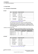
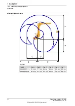
Page 62: ...o need for rewinding the axis Limitations for wall mounted robots The axis 1 working range has the following limitations for wall mounted robots Max combined pay arm load kg for 180o working range axis 1 Working range axis 1 with max payload max arm load Max arm load kg Max pay load kg Robot variant 8 45o 11 20 IRB 2600 20 1 65 8 45o 16 12 IRB 2600 12 1 65 40o 11 12 IRB 2600 12 1 85 IRB 2600ID Ran...

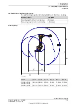
Page 63: ...ng range for axis 1 at wall mounting Working range xx0800000267 Pos F Pos E Pos D Pos C Pos B Pos A Variant 1653 mm 1353 mm 469 mm 837 mm 993 mm 1948 mm IRB 2600 20 1 65 IRB 2600 12 1 65 1853 mm 1553 mm 506 mm 967 mm 1174 mm 2148 mm IRB 2600 12 1 85 Continues on next page Product specification IRB 2600 63 3HAC035959 001 Revision AA Copyright 2009 2021 ABB All rights reserved 1 Description 1 8 1 In...

Page 64: ...mm 1550 mm 542 mm 936 mm 1171 mm 2145 mm IRB 2600ID 15 1 85 2000 mm 1700 mm 539 mm 1051 mm 1321 mm 2295 mm IRB 2600ID 8 2 00 64 Product specification IRB 2600 3HAC035959 001 Revision AA Copyright 2009 2021 ABB All rights reserved 1 Description 1 8 1 Introduction to Robot Motion Continued ...

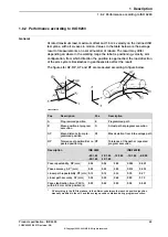
Page 65: ...cution B Max deviation from E to average path AT Mean distance from pro grammed position AP Tolerance of the path at repeated program execution RT Tolerance of position B at re peated positioning RP IRB 2600ID IRB 2600 Description 8 2 00 15 1 85 12 1 85 12 1 65 12 1 65 20 1 65 20 1 65 0 023 0 026 0 04 0 04 0 04 Pose repeatability RP mm 0 033 0 014 0 03 0 03 0 03 Pose accuracy APi mm 0 27 0 30 0 16...

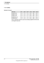
Page 66: ... 360 s 360 s 175 s 175 s 175 s IRB 2600 12 1 85 500 s 360 s 360 s 175 s 175 s 175 s IRB 2600ID 15 1 85 500 s 360 s 360 s 175 s 175 s 175 s IRB 2600ID 8 2 00 There is a supervision function to prevent overheating in applications with intensive and frequent movements 66 Product specification IRB 2600 3HAC035959 001 Revision AA Copyright 2009 2021 ABB All rights reserved 1 Description 1 8 3 Velocity ...

Page 67: ...gory 1 stops as required by EN ISO 10218 1 Annex B are listed in Product specification Robot stopping distances according to ISO 10218 1 3HAC048645 001 Product specification IRB 2600 67 3HAC035959 001 Revision AA Copyright 2009 2021 ABB All rights reserved 1 Description 1 8 4 Robot stopping distances and times ...

Page 68: ...4 Fan failure stops the robot To determine the use of cooling fans for axis 1 and or axis 2 motor use the Gearbox Heat Prediction Tool in RobotStudio Reliable facts for the decision of need for fan or not will be achieved by entering the ambient temperature for a specific cycle Please contact your local ABB organization 68 Product specification IRB 2600 3HAC035959 001 Revision AA Copyright 2009 20...

Page 69: ...of the upper arm Note The maximum leakage current for attached equipment must not exceed 10mA The customer connections are located on the robot as shown in the figure Customer connections on upper arm A B C D xx2000001657 R2 PROC1 A Air M16x1 5 24 cone sealing R2 ETHERNET B R2 CP or R2 CBUS C R2 CS or R2 CP CS D Continues on next page Product specification IRB 2600 69 3HAC035959 001 Revision AA Co...

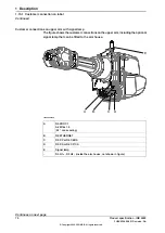
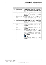
Page 70: ... house A B C D E xx2000001658 R2 PROC1 A Air M16x1 5 24 cone sealing R2 ETHERNET B R2 CP or R2 CBUS C R2 CS or R2 CP CS D Signal lamp E R3 H1 R3 H2 inside the arm house not shown in figure Continues on next page 70 Product specification IRB 2600 3HAC035959 001 Revision AA Copyright 2009 2021 ABB All rights reserved 1 Description 1 10 1 Customer connection on robot Continued ...

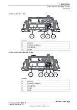
Page 71: ...mer connections base with 7th axis A B E C D xx2000001637 R1 CP CS A R1 PROC1 Air M16x1 5 B R1 ETHERNET C R1 SMB D R2 FB7 E Continues on next page Product specification IRB 2600 71 3HAC035959 001 Revision AA Copyright 2009 2021 ABB All rights reserved 1 Description 1 10 1 Customer connection on robot Continued ...

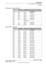
Page 72: ...nection sets To connect power and signal conductors to the robot base upper arm connectors the following parts are recommended Content Art no Connector Connection set Sockets for cable area of 0 14 2 5 mm Hood foundry Hinged frame hood Multicontact module female 3HAC16667 1 R1 CP CS PROC1 on base Hose coupling M12 connector male 3HAC033181 001 R1 ETHER NET Connector set on base Pins for cable area...

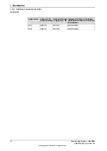
Page 73: ...S b1 R2 CS A XP5 1 1 CSA R1 CP CS b2 R2 CS B XP5 1 2 CSB R1 CP CS b3 R2 CS C XP5 2 1 CSC R1 CP CS b4 R2 CS D XP5 2 2 CSD R1 CP CS b5 R2 CS E XP5 2 3 CSE R1 CP CS b6 R2 CS F XP5 2 4 CSF R1 CP CS b7 R2 CS G XP5 1 9 CSG R1 CP CS b8 R2 CS H XP5 1 10 CSH R1 CP CS b9 R2 CS J XP5 1 11 CSJ R1 CP CS b10 R2 CS K XP5 1 12 CSK R1 CP CS b11 R2 CS L XP5 1 3 CSL R1 CP CS b12 R2 CS M XP5 1 4 CSM R1 CP CS b13 R2 C...

Page 74: ...act on Upper arm R2 Customer Ter minal Controller Signal name R1 CP CS b23 R2 CS Y XP5 2 10 CSY R1 CP CS b24 R2 CS Z XP5 2 11 CSZ 74 Product specification IRB 2600 3HAC035959 001 Revision AA Copyright 2009 2021 ABB All rights reserved 1 Description 1 10 1 Customer connection on robot Continued ...

Page 75: ...tions The same option numbers are used here as in the specification form The variants and options related to the robot controller are described in the product specification for the controller Product specification IRB 2600 75 3HAC035959 001 Revision AA Copyright 2009 2021 ABB All rights reserved 2 Specification of variants and options 2 1 Introduction to variants and options ...

Page 76: ...n IRB 2600 IP 67 Standard 287 4 IRB 2600ID upper arm IP 54 See Protection type Foundry Plus 2 on page 11 for a com plete description of protection type Foundry Plus 2 Foundry Plus 2 287 3 Not valid for IRB 2600ID versions Mounting position Description Option Inverted mounting of the manipulator 224 2 Not together with option 603 1 Absolute Accuracy Note Manipulators delivered for floor mounting mu...

Page 77: ...US 803 4 Connector kit The kit consists of connectors pins and sockets Description Option For the connectors on the upper arm 431 1 For the connectors on the foot if connection to manipulator 239 1 Flexible conduit Protection hose for customer signals power and hoses Only valid for IRB 2600ID xx1000000982 Description Pos Flexible conduit option 943 1 A Safety lamp Description Option Safety lamp sa...

Page 78: ...n Cooling fan for axis 1 motor option 87 1 A Cooling fan for axis 2 motor option 88 1 B Protection cover C Resolver connection axis 7 A connector for resolver signals for axis 7 located on the base Remark Description Option Used together with first additional drive option 907 1 On base 864 1 Continues on next page 78 Product specification IRB 2600 3HAC035959 001 Revision AA Copyright 2009 2021 ABB...

Page 79: ...of 22 5 from the synchronization position between values defined in the table The values differ depending on which design of the gearbox and base the robot is equipped with Limitation in mechanical turning range calculated from synchronization position Robot variant 126 to 13 5 in steps of 22 5 IRB 2600 Type C 20 1 65 IRB 2600 Type C 12 1 65 129 to 16 5 in steps of 22 5 IRB 2600 20 1 65 IRB 2600 1...

Page 80: ... and labour to repair or replace the non conforming portion of the equipment without additional charges During that period it is required to have a yearly Preventative Maintenance according to ABB manuals to be performed by ABB If due to customer restrains no data can be analyzed in the ABB Ability service Condition Monitoring Diagnostics for robots with OmniCore controllers and ABB has to travel ...

Page 81: ...ice in case of other requirements Standard warranty 24 months 438 5 Standard warranty extended with 6 months from end date of the standard warranty Warranty terms and con ditions apply Standard warranty 6 months 438 6 Standard warranty extended with 30 months from end date of the standard warranty Warranty terms and con ditions apply Standard warranty 30 months 438 7 Maximum 6 months postponed sta...

Page 82: ...rding positioners see Product specification IRBP D2009 3HAC038208 001 82 Product specification IRB 2600 3HAC035959 001 Revision AA Copyright 2009 2021 ABB All rights reserved 2 Specification of variants and options 2 3 Positioners ...

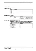
Page 83: ...nection of Parallel CAN DeviceNet communication Following information specifies the cable length for Parallel CAN DeviceNet Ethernet PROFIBUS floor cables for connections between cabinets and manipulator Lenghts m Option 7 94 1 90 2 859 1 92 2 15 94 2 90 3 859 2 92 3 22 90 4 859 3 92 4 30 94 4 90 5 859 4 92 5 Product specification IRB 2600 83 3HAC035959 001 Revision AA Copyright 2009 2021 ABB All ...

Page 84: ...Combi I O is needed for WeldGuide functions Requires option WeldGuide MultiPass 815 2 Basic 958 1 Only together with ArsitoMig 4000i 5000i MigRob and TPS power sources Digital I O or AD Combi I O is needed for WeldGuide functions Requires option WeldGuide MultiPass 815 2 Advanced 958 2 Installation kit Description Type Option See Product specification Controller IRC5 with FlexPendant list of varia...

Page 85: ...C96 1037 2 BullsEye stand alone BullsEye 1037 5 Torch service options Description Type Option Extension pedestal for TSC TC BullsEye Extension pedestal 1038 1 Product specification IRB 2600 85 3HAC035959 001 Revision AA Copyright 2009 2021 ABB All rights reserved 2 Specification of variants and options 2 6 Process equipment ...

Page 86: ...etail including service and safety instructions Tip All documents can be found via myABB Business Portal www abb com myABB 86 Product specification IRB 2600 3HAC035959 001 Revision AA Copyright 2009 2021 ABB All rights reserved 2 Specification of variants and options 2 7 User documentation ...

Page 87: ...ions of axis 1 and axis 2 gearboxes on page 88 IRB 2600ID IRB 2600 standard variants motor type A motor type A Initial version Axis 1 5 change to motor type B Axis 2 changes gearbox IRB 2600 Type A Axis 6 keeps motor type A Axis 1 6 change to motor type B IRB 2600 Type B Axis 1 and 2 changes gearbox and motor pinion IRB 2600 Type C only IRB 2600 Type C 20 1 65 IRB 2600 Type C 12 1 65 Axis 3 4 5 an...

Page 88: ...C 20 1 65 IRB 2600 Type C 12 1 65 supplier Nabtesco gearbox option 1564 2 The different versions affect the surrounding mechanical structure of the robot Following parts are unique for each version of the gearbox Axis 1 gearbox Axis 2 gearbox Frame Base Lower arm Axis 1 motor pinion Axis 2 motor pinion Cable harness The listed parts are not interchangeable The gearbox oils are not interchangeable ...

Page 89: ... Type C variant of the robot informing that the robot is a Type C variant xx1800002211 Continues on next page Product specification IRB 2600 89 3HAC035959 001 Revision AA Copyright 2009 2021 ABB All rights reserved 3 Robot description 3 2 Non compatible versions of axis 1 and axis 2 gearboxes Continued ...

Page 90: ...low the motor flange A The bushing for the calibration tool is loc ated to the right on the base The bushing for the calibration tool is centered on the base The oil plug for drainage is located in front of the gearbox when robot is standing in synchronization position The oil plug for drainage is located on the left side of the gearbox and visible through an opening in the frame when robot is sta...

Page 91: ... Article number axis 1 gear box Robot variant 3HAC039109 001 3HAC028837 001 IRB 2600 20 1 65 3HAC043134 001 3HAC043130 001 IRB 2600 Type C 20 1 65 3HAC039109 001 3HAC028837 001 IRB 2600 12 1 65 3HAC043134 001 3HAC043130 001 IRB 2600 Type C 12 1 65 Identifying the gearbox version on the FlexPendant The robot type is found on the System Info view on the FlexPendant Expand System properties Drive mod...

Page 92: ...This page is intentionally left blank ...

Page 93: ...manipulator Basic software and software options for robot and PC For more information see Product specification Controller IRC5 Robot peripherals Track Motion Motor Units Positioners Product specification IRB 2600 93 3HAC035959 001 Revision AA Copyright 2009 2021 ABB All rights reserved 4 Accessories 4 1 Introduction to accessories ...

Page 94: ...This page is intentionally left blank ...

Page 95: ...entation 86 E Electronic Position Switches 79 EPS 79 F fine calibration 33 I instructions 86 M manuals 86 O options 75 P product standards 20 S safety standards 20 service instructions 86 standards 20 ANSI 20 CAN 20 EN IEC 20 EN ISO 20 standard warranty 80 stock warranty 80 stopping distances 67 stopping times 67 U user documentation 86 V variants 75 W warranty 80 Product specification IRB 2600 95...

Page 96: ......

Page 97: ......
Page 98: ...47 22 87 2000 ABB Engineering Shanghai Ltd Robotics Discrete Automation No 4528 Kangxin Highway PuDong District SHANGHAI 201319 China Telephone 86 21 6105 6666 ABB Inc Robotics Discrete Automation 1250 Brown Road Auburn Hills MI 48326 USA Telephone 1 248 391 9000 abb com robotics 3HAC035959 001 Rev AA en Copyright 2009 2021 ABB All rights reserved Specifications subject to change without notice ...

Reviews: