Note
Action
CAUTION
Always cut the paint with a knife and grind
the paint edge when disassembling parts.
See
Cut the paint or surface on the robot
before replacing parts on page 201
2
CAUTION
The gearbox weighs 51 kg
All lifting accessories used must be sized
accordingly!
3
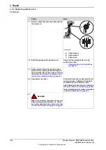
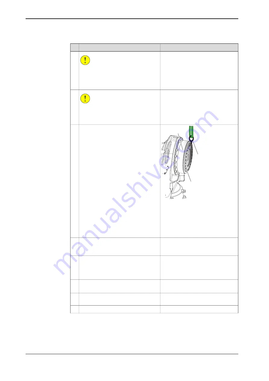
A
B
C
xx0800000445
Fit a
lifting lug
in the uppermost hole for
the attachment screws securing the lower
arm to the gearbox.
4
Parts:
•
A: Gearbox axis 2
•
B: Lifting lug
•
C: Holes for attachment screws
securing the lower arm to gearbox
axis 2.
Clean all assembly surfaces.
5
Remove any painting from the assembly
surfaces, with a knife.
O-ring, nitrile rubber: 3HAB3772-120.
Apply some grease on the o-ring before fit-
ting.
6
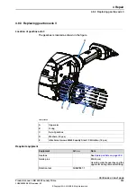
See the figure in:
•
Location of gearbox axis 2 on
page 336
Valid for Type C:
Replace if damaged.
Guide pin, M12x150: 3HAC13056-2
Fit two guide pins in opposite holes in the
frame.
7
Always use guide pins in pairs.
Secure the gearbox with a roundsling in an
overhead crane or similar.
8
Release the brakes of the axis 2 motor.
9
Continues on next page
342
Product manual - IRB 4600 Foundry Prime
3HAC040585-001 Revision: M
© Copyright 2013-2018 ABB. All rights reserved.
4 Repair
4.8.2 Replacing gearbox axis 2
Continued
Summary of Contents for IRB 4600 Foundry Prime
Page 1: ...ROBOTICS Product manual IRB 4600 Foundry Prime ...
Page 106: ...This page is intentionally left blank ...
Page 194: ...This page is intentionally left blank ...
Page 398: ...This page is intentionally left blank ...
Page 400: ...This page is intentionally left blank ...
Page 406: ......
Page 407: ......


