Connecting Signals
Installation and Commissioning
62
Product Manual IRB 6400R
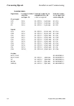
3.16.2 Sensors
Sensors are connected to one optional digital unit.
Technical data
See Product Specification IRB 6400, chapter 3.10.
The following sensors can be connected:
Sensor type
Signal level
Digital one bit sensors
High
“1”
Low
“0”
Digital two bit sensors
High
“01”
No signal
“00”
Low
“10”
Error status
“11” (stop program running)
3.16.3 Connection and address keying of the CAN-bus
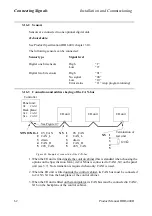
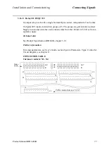
Figure 46 Example of connection of the CAN-bus
1. When the I/O unit is fitted inside the control cabinet (this is standard when choosing the
options on the Specification form), its CAN bus is connected to CAN1, X9 on the panel
unit (see 3.7). No termination is required when only CAN1 is used.
2. When the I/O unit is fitted outside the control cabinet, its CAN bus must be connected
to CAN3, X10 on the backplane of the control cabinet.
3. When the I/O unit is fitted on the manipulator, its CAN bus must be connected to CAN2,
X16 on the backplane of the control cabinet.
Panel unit:
X9
CAN1
Back plane:
X10
CAN3
X16
CAN2
Controller
X9/X10/X16. 1 0V_CAN
2 CAN_L
3 drain
4 CAN_H
5 24V_CAN
I/O unit
I/O unit
I/O unit
X5. 1
0V_CAN
2
CAN_L
3
drain
4
CAN_H
5
24V_CAN
X5. 1
2
3
4
5
120
Ω
Termination of
last unit
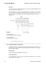
See Figure 47.
Summary of Contents for IRB 6400R
Page 4: ...Description 20 Product Specification IRB 1400 M97A BaseWare OS 3 0 ...
Page 6: ...Introduction 2 Product Manual ...
Page 10: ...Introduction 6 Product Manual ...
Page 12: ...Product Specification IRB 6400R 2 Product Specification IRB 6400R M99 BaseWare OS 3 2 ...
Page 78: ...Accessories 68 Product Specification IRB 6400R M99 BaseWare OS 3 2 ...
Page 80: ...Product Specification RobotWare 2 Product Specification RobotWare for BaseWare OS 3 2 ...
Page 82: ...Introduction 4 Product Specification RobotWare for BaseWare OS 3 2 ...
Page 104: ...Interbus S 3 2 26 Product Specification RobotWare for BaseWare OS 3 2 ...
Page 110: ...I O Plus 3 2 32 Product Specification RobotWare for BaseWare OS 3 2 ...
Page 128: ...PalletWare 50 Product Specification RobotWare for BaseWare OS 3 2 ...
Page 132: ...Safety 2 Product Manual ...
Page 148: ...System Description CONTENTS Page 2 Product Manual ...
Page 158: ...Structure System Description 12 Product Manual ...
Page 160: ...Computer System System Description 14 Product Manual ...
Page 164: ...I O System System Description 18 Product Manual ...
Page 168: ...Safety System System Description 22 Product Manual ...
Page 170: ...External Axes System Description 24 Product Manual ...
Page 174: ...Installation and Commissioning CONTENTS Page 4 Product Manual IRB 6400R ...
Page 196: ...On Site Installation Installation and Commissioning 26 Product Manual IRB 6400R ...
Page 270: ...Installing the Control Program Installation and Commissioning 100 Product Manual IRB 6400R ...
Page 292: ...Maintenance CONTENTS Page 2 Product Manual IRB 6400R ...
Page 299: ...Maintenance Product Manual IRB 6400R 9 Figure 4 Lubricating gearbox axis 1 4 3 1 2 ...
Page 312: ...Troubleshooting Tools CONTENTS Page 2 Product Manual ...
Page 350: ...Troubleshooting Tools 40 Product Manual ...
Page 352: ...Fault tracing guide 2 Product Manual ...
Page 362: ...Fault tracing guide 12 Product Manual ...
Page 375: ...Motor units Repairs 12 Product Manual IRB 6400R ...
Page 401: ...Arm System Repairs 38 Product Manual IRB 6400R ...
Page 409: ...Cabling Repairs 46 Product Manual IRB 6400R ...
Page 441: ...Special Tools List Repairs 80 Product Manual IRB 6400R ...
Page 479: ...Part List and Spare Parts Product Manual IRB 6400R 38 ...
Page 480: ...Part List and Spare Parts Product Manual IRB 6400R 39 ...
Page 481: ...Part List and Spare Parts Product Manual IRB 6400R 40 ...


