Note
Action
Shown in the figure
of the upper arm components on page 192
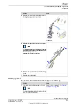
Remove the shaft, axis 3 (B):
1
Remove the
lock nut
(K).
2
Remove the
set screw
(C) holding
the
shaft
.
3
Put the
adapter
on the
shaft
.
4
Remove the shaft.
12
Perform the removal with care. Threads
can otherwise be damaged!
Art.no. is specified in
Shown in the figure
of the upper arm components on page 192
Note
The adapter is not needed on this shaft!
Then remove the
shaft, axis 2
(A) in the
same order:
1
Remove the
lock nut
(K)
2
Remove the
set screw
(C) holding
the shaft
3
Remove the
shaft axis 2
.
13
Put the
shafts
in a clean and safe place.
14
Remove the
upper arm
.
15
Continues on next page
Product manual - IRB 660
195
3HAC025755-001 Revision: W
© Copyright 2006-2020 ABB. All rights reserved.
4 Repair
4.4.3 Replacement of upper arm
Continued
Summary of Contents for IRB 660
Page 1: ...ROBOTICS Product manual IRB 660 ...
Page 8: ...This page is intentionally left blank ...
Page 332: ...This page is intentionally left blank ...
Page 352: ...This page is intentionally left blank ...
Page 354: ...This page is intentionally left blank ...
Page 360: ......
Page 361: ......


