[542] ScreenViewer
Product Specification RobotWare Options for BaseWare OS 4.0
9
[542] ScreenViewer
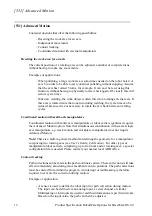
This option adds a user window to display user defined screens with advanced display
functions. The user window can be displayed at any time, regardless of the execution
state of the RAPID programs.
User defined screens
The user defined screens are composed of:
• A fixed background with a size of 12 lines of 40 characters each. These characters
can be ASCII and/or horizontal or vertical strokes (for underlining, separating or
framing).
• 1 to 5 function keys.
• 1 to 4 pop-up menus containing from 1 to 10 choices.
• 1 to 30 display and input fields defined by:
- Their position and size.
- Their type (display, input).
- Their display format (integer, decimal, binary, hexadecimal, text).
- A possible boundary with minimum and maximum limits.
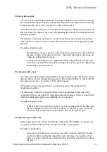
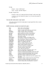
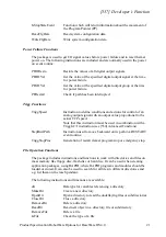
Example of a user defined screen. The ### represent the fields.
Advanced Display functions
The user defined screens run independently of the RAPID programs.
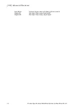
Some events occur on a screen (new screen displayed, menu choice selected, function
key pressed, field modified, ...). A list of user screen commands can be associated with
any of these events, then when the event occurs, the command list will be executed.
|
X
T
| ##
| ##
| ##
| ##
| ##
| ##
| ##
| ##
Program number: ###
SpotTim
File
View
Next
Prev.
(Copy)
Valid
PHASES
SQUEEZE
PREHEAT
COOLING
## HEAT
COLD
LASTCOLD
POSTHEAT
HOLD
Heat stepper: ###
interpolated: ##
| START
|
| ####
|
| ####
|
|
| ####
|
| END
|
|
| ####
|
|
|
| ####
|
| Tolerance: ###%
| Force: ###daN
| Forge: ###daN
|
| Fire chck: ###
|
| Err allow: ###%
| Numb err: ###
| CURENT (A)
|
Summary of Contents for IRB 6600 - 175/2.55
Page 2: ......
Page 6: ...Product Specification IRB 6600 2 Product Specification IRB 6600 M2000 ...
Page 82: ...Specification of Variants and Options 78 Product Specification IRB 6600 M2000 ...
Page 84: ...Accessories 80 Product Specification IRB 6600 M2000 ...
Page 116: ...Description 30 Product Specification S4Cplus M2000 BaseWare OS 4 0 ...
Page 136: ...Specification of Variants and Options 50 Product Specification S4Cplus M2000 BaseWare OS 4 0 ...
Page 140: ...Index 54 Product Specification S4Cplus M2000 BaseWare OS 4 0 ...
Page 141: ...Product Specification RobotWare Options 3HAC 9218 1 Rev 2 BaseWare OS 4 0 ...
Page 146: ...Introduction 4 Product Specification RobotWare Options for BaseWare OS 4 0 ...
Page 201: ...Installation Manual IRB 6600 6650 M2000A 3HAC 16245 1 Revision A ...
Page 218: ...1 Safety service 1 3 7 Work inside the manipulator s working range 16 A 3HAC 16245 1 ...
Page 237: ...4 On site Installation 3HAC 16245 1 A 35 Chapter 4 On site Installation ...
Page 277: ...5 Electrical connections 3HAC 16245 1 A 75 Chapter 5 Electrical connections ...
Page 376: ...9 System directory structure 9 0 5 Handling mass memory storage capacity 174 A 3HAC 16245 1 ...
Page 406: ...10 Calibration 10 5 5 Retrieving offset values 204 A 3HAC 16245 1 ...
Page 410: ......
Page 411: ...Repair Manual part 1 IRB 6600 6650 M2000A 3HAC 16247 1 Revision A ...
Page 416: ...Table of Contents iv 3HAC 16247 1 ...
Page 418: ...0 0 1 Overview 2 A 3HAC 16247 1 ...
Page 428: ...1 Safety service 1 3 7 Work inside the manipulator s working range 12 A 3HAC 16247 1 ...
Page 570: ...3 Repair activities manipulator 3 6 8 Refitting of gearbox axis 6 154 A 3HAC 16247 1 ...
Page 616: ...5 Appendix 1 Part Lists 5 1 15 Arm extension set 450 mm 3HAC 12311 5 200 A 3HAC 16247 1 ...
Page 618: ...6 Appendix 2 Foldouts 6 0 1 Introduction 202 A 3HAC 16247 1 ...
Page 620: ...6 Appendix 2 Foldouts 6 0 2 Base incl Frame 204 A 3HAC 16247 1 ...
Page 622: ...6 Appendix 2 Foldouts 6 0 3 Frame Lower arm 1 206 A 3HAC 16247 1 ...
Page 624: ...6 Appendix 2 Foldouts 6 0 4 Frame Lower arm 2 208 A 3HAC 16247 1 ...
Page 626: ...6 Appendix 2 Foldouts 6 0 5 Upper arm 210 A 3HAC 16247 1 ...
Page 628: ...6 Appendix 2 Foldouts 6 0 6 Wrist complete 212 A 3HAC 16247 1 ...
Page 630: ......
Page 631: ...Maintenance Manual IRB 6600 6650 M2000A 3HAC 16246 1 Revision A ...
Page 636: ...0 0 1 Overview 2 A 3HAC 16246 1 ...
Page 646: ...1 Safety service 1 3 7 Work inside the manipulator s working range 12 A 3HAC 16246 1 ...
Page 740: ...6 Maintenance activities controller cabinet 6 3 5 Cleaning Drain filter 106 A 3HAC 16246 1 ...
Page 742: ......
Page 743: ...Repair Manual part 2 Circuit Diagrams IRB 6600 6650 M2000A 3HAC 16247 1 Revision A ...
Page 746: ...0 0 1 Overview 2 A 3HAC 16247 1 ...
Page 748: ......
Page 749: ...Revision No of sheets sheet 20 Circuit Diagram 3HAC 13347 1 Contents 101 01 ...
Page 750: ......
Page 751: ...Revision No of sheets sheet 20 Circuit Diagram 3HAC 13347 1 Connection Point Location 102 01 ...
Page 752: ......
Page 753: ...Revision No of sheets sheet 20 Circuit Diagram 3HAC 13347 1 Legend 103 01 ...
Page 754: ......
Page 755: ...Revision No of sheets sheet 20 Circuit Diagram 3HAC 13347 1 Brake Release Unit 104 01 ...
Page 756: ......
Page 758: ......
Page 759: ...Revision No of sheets sheet 20 Circuit Diagram 3HAC 13347 1 Serial Measurement Board 105 01 ...
Page 760: ......
Page 761: ...Revision No of sheets sheet 20 Circuit Diagram 3HAC 13347 1 Axis 1 106 01 ...
Page 762: ......
Page 763: ...Revision No of sheets sheet 20 Circuit Diagram 3HAC 13347 1 Axis 2 107 01 ...
Page 764: ......
Page 765: ...Revision No of sheets sheet 20 Circuit Diagram 3HAC 13347 1 Axis 3 108 01 ...
Page 766: ......
Page 767: ...Revision No of sheets sheet 20 Circuit Diagram 3HAC 13347 1 Axis 4 109 01 ...
Page 768: ......
Page 769: ...Revision No of sheets sheet 20 Circuit Diagram 3HAC 13347 1 Axis 5 IRB 7600 110 01 ...
Page 770: ......
Page 771: ...Revision No of sheets sheet 20 Circuit Diagram 3HAC 13347 1 Axis 5 IRB 6600 110 1 01 ...
Page 772: ......
Page 773: ...Revision No of sheets sheet 20 Circuit Diagram 3HAC 13347 1 Axis 6 111 01 ...
Page 774: ......
Page 776: ......
Page 778: ......
Page 780: ......
Page 781: ...Revision No of sheets sheet 20 Circuit Diagram 3HAC 13347 1 Switches axis 1 113 01 ...
Page 782: ......
Page 783: ...Revision No of sheets sheet 20 Circuit Diagram 3HAC 13347 1 Switches Fan axis 2 114 01 ...
Page 784: ......
Page 785: ...Revision No of sheets sheet 20 Circuit Diagram 3HAC 13347 1 Switches Fan axis 3 115 01 ...
Page 786: ......
Page 787: ...Revision No of sheets sheet 20 Circuit Diagram 3HAC 13347 1 Weld connections 116 01 ...
Page 792: ...Circuit Diagram 3HAC 5582 2 Rev 03 Contents Page 4 Circuit Diagram S4Cplus ...
Page 793: ...Revision 04 No of sheets sheet 1 0 107 Circuit Diagram 3HAC 5582 2 1 General Information ...
Page 794: ......
Page 795: ...Revision 04 No of sheets sheet 1 1 91 Circuit Diagram 3HAC 5582 2 Block Diagram ...
Page 796: ......
Page 797: ...Revision 04 No of sheets sheet 1 2 91 Circuit Diagram 3HAC 5582 2 View of Control Cabinet ...
Page 798: ......
Page 799: ...Revision 04 No of sheets sheet 1 3 91 Circuit Diagram 3HAC 5582 2 View of Control Cabinet ...
Page 800: ......
Page 801: ...Revision 04 No of sheets sheet 1 4 91 Circuit Diagram 3HAC 5582 2 Designation ...
Page 802: ......
Page 803: ...Revision 04 No of sheets sheet 1 5 91 Circuit Diagram 3HAC 5582 2 Designation ...
Page 804: ......
Page 806: ......
Page 807: ...Revision 04 No of sheets sheet 2 1 107 Circuit Diagram 3HAC 5582 2 Mains Connection ...
Page 808: ......
Page 809: ...Revision 04 No of sheets sheet 2 2 107 Circuit Diagram 3HAC 5582 2 Transformer Unit 400 600V ...
Page 810: ......
Page 811: ...Revision 04 No of sheets sheet 2 3 107 Circuit Diagram 3HAC 5582 2 Transformer unit 200 440V ...
Page 812: ......
Page 813: ...Revision 04 No of sheets sheet 2 4 107 Circuit Diagram 3HAC 5582 2 Power Supply ...
Page 814: ......
Page 816: ......
Page 818: ......
Page 820: ......
Page 821: ...Revision 04 No of sheets sheet 3 1 91 Circuit Diagram 3HAC 5582 2 Block Diagram Computer Unit ...
Page 822: ......
Page 823: ...Revision 04 No of sheets sheet 3 2 91 Circuit Diagram 3HAC 5582 2 Cabling in Computer Unit ...
Page 824: ......
Page 826: ......
Page 827: ...Revision 04 No of sheets sheet 3 4 91 Circuit Diagram 3HAC 5582 2 Computer Cooling ...
Page 828: ......
Page 830: ......
Page 832: ......
Page 834: ......
Page 835: ...Revision 04 No of sheets sheet 3 8 91 Circuit Diagram 3HAC 5582 2 Base Connector Unit ...
Page 836: ......
Page 838: ......
Page 840: ......
Page 841: ...Revision 04 No of sheets sheet 4 1 107 Circuit Diagram 3HAC 5582 2 Emergency Stop ...
Page 842: ......
Page 844: ......
Page 846: ......
Page 848: ......
Page 850: ......
Page 851: ...Revision 04 No of sheets sheet 5 1 107 Circuit Diagram 3HAC 5582 2 Block Diagram ...
Page 852: ......
Page 853: ...Revision 04 No of sheets sheet 5 2 107 Circuit Diagram 3HAC 5582 2 Rectifier Fans and Bleeder ...
Page 854: ......
Page 856: ......
Page 858: ......
Page 859: ...Revision 04 No of sheets sheet 5 5 107 Circuit Diagram 3HAC 5582 2 Servo Drive Units IRB 140 ...
Page 860: ......
Page 861: ...Revision 04 No of sheets sheet 5 6 107 Circuit Diagram 3HAC 5582 2 Servo Drive Units IRB 340 ...
Page 862: ......
Page 864: ......
Page 866: ......
Page 868: ......
Page 870: ......
Page 871: ...Revision 04 No of sheets sheet 5 11 107 Circuit Diagram 3HAC 5582 2 Control Cable IRB 140 ...
Page 872: ......
Page 874: ......
Page 876: ......
Page 878: ......
Page 880: ......
Page 882: ......
Page 884: ......
Page 885: ...Revision 04 No of sheets sheet 6 0 107 Circuit Diagram 3HAC 5582 2 6 External Axes ...
Page 886: ......
Page 887: ...Revision 04 No of sheets sheet 107 6 1 Circuit Diagram 3HAC 5582 2 External Axes ...
Page 888: ......
Page 890: ......
Page 892: ......
Page 894: ......
Page 896: ......
Page 898: ......
Page 900: ......
Page 902: ......
Page 904: ......
Page 906: ......
Page 907: ...Revision 04 No of sheets sheet 107 6 11 Circuit Diagram 3HAC 5582 2 DDU Cable IRB 6600 7600 ...
Page 908: ......
Page 910: ......
Page 912: ......
Page 914: ......
Page 916: ......
Page 917: ...Revision 04 No of sheets sheet 107 7 1 Circuit Diagram 3HAC 5582 2 I O Unit Position ...
Page 918: ......
Page 920: ......
Page 922: ......
Page 924: ......
Page 926: ......
Page 928: ......
Page 929: ...Revision 04 No of sheets sheet 107 7 7 Circuit Diagram 3HAC 5582 2 Relay I O Unit Input 1 16 ...
Page 930: ......
Page 932: ......
Page 934: ......
Page 935: ...Revision 04 No of sheets sheet 107 7 10 Circuit Diagram 3HAC 5582 2 Analogue I O Unit ...
Page 936: ......
Page 938: ......
Page 939: ...Revision 04 No of sheets sheet 107 7 12 Circuit Diagram 3HAC 5582 2 Interbus S Slave ...
Page 940: ......
Page 941: ...Revision 04 No of sheets sheet 107 7 13 Circuit Diagram 3HAC 5582 2 Profibus DP Slave ...
Page 942: ......
Page 943: ...Revision 04 No of sheets sheet 107 7 14 Circuit Diagram 3HAC 5582 2 Encoder Unit ...
Page 944: ......
Page 945: ...Revision 04 No of sheets sheet 107 7 15 Circuit Diagram 3HAC 5582 2 Profibus DP Master Slave ...
Page 946: ......
Page 948: ......
Page 949: ...Revision 04 No of sheets sheet 8 0 107 Circuit Diagram 3HAC 5582 2 8 Other Options ...
Page 950: ......
Page 951: ...Revision 04 No of sheets sheet 107 8 1 Circuit Diagram 3HAC 5582 2 Floppy Disk ...
Page 952: ......
Page 953: ...Revision 04 No of sheets sheet 107 8 2 Circuit Diagram 3HAC 5582 2 Service Equipment Supply ...
Page 954: ......
Page 956: ......
Page 958: ......
Page 960: ......
Page 962: ......
Page 964: ......
Page 965: ...Revision 04 No of sheets sheet 107 8 8 Circuit Diagram 3HAC 5582 2 External Control Panel ...
Page 966: ......
Page 968: ......
Page 969: ...Revision 04 No of sheets sheet 107 8 10 Circuit Diagram 3HAC 5582 2 Time Relay ...
Page 970: ......
Page 972: ......
Page 974: ......
Page 975: ...Revision 04 No of sheets sheet 107 8 13 Circuit Diagram 3HAC 5582 2 LAN Ethernet connection ...
Page 976: ......
Page 978: ......
Page 980: ......
Page 982: ......
Page 984: ......
Page 986: ......
Page 988: ......
Page 989: ...Revision 04 No of sheets sheet 9 0 107 Circuit Diagram 3HAC 5582 2 9 External Axis Cabinet ...
Page 990: ......
Page 991: ...Revision 04 No of sheets sheet 107 9 1 Circuit Diagram 3HAC 5582 2 Block Diagram ...
Page 992: ......
Page 994: ......
Page 995: ...Revision 04 No of sheets sheet 107 9 3 Circuit Diagram 3HAC 5582 2 Designation ...
Page 996: ......
Page 997: ...Revision 04 No of sheets sheet 107 9 4 Circuit Diagram 3HAC 5582 2 Mains Connection ...
Page 998: ......
Page 999: ...Revision 04 No of sheets sheet 107 9 5 Circuit Diagram 3HAC 5582 2 Transformer Unit ...
Page 1000: ......
Page 1001: ...Revision 04 No of sheets sheet 107 9 6 Circuit Diagram 3HAC 5582 2 Power Supply I O Supply ...
Page 1002: ......
Page 1003: ...Revision 04 No of sheets sheet 107 9 7 Circuit Diagram 3HAC 5582 2 Power Unit ...
Page 1004: ......
Page 1005: ...Revision 04 No of sheets sheet 107 9 8 Circuit Diagram 3HAC 5582 2 Rectifier Fans and Bleeder ...
Page 1006: ......
Page 1008: ......
Page 1010: ......
Page 1012: ......
Page 1014: ......
Page 1016: ......
Page 1018: ......
Page 1019: ...Revision 04 No of sheets sheet 107 9 15 Circuit Diagram 3HAC 5582 2 Service Equipment Supply ...


