4 Repair
4.7.2. Replacement of gearbox axis 2
395
3HAC023082-001 Revision: E
©
Co
py
rig
h
t 200
4-
200
8 ABB. All righ
ts reser
v
ed.
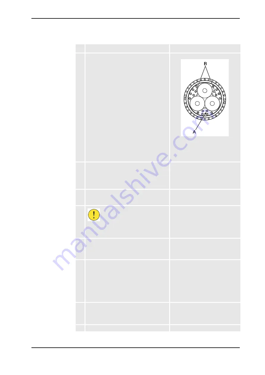
4. Fit the
guide pins, sealing axis 2/3
to the rear
of the gearbox, axis 2.
Use the attachment holes shown in the figure
to the right!
xx0300000552
•
A: Rear attachment screws,
gearbox (18 pcs)
•
B: Holes for the guide pins,
sealing axis 2/3 on the gearbox
5. Fit the new
sealing, axis 2/3
on to the guide
pins on the gearbox.
Note!
Do not remove the guide pins for the
sealing until the rear attachment screws are
secured.
Art. no. is specified in
!
6. Fit two
guide pins, M12
in 180° relation to each
other in the frame, in the screw holes for the
gearboxes front attachment screws.
Art. no. is specified in
!
7.
CAUTION!
The gearbox weighs 100 kg! All lifting
equipment used must be sized accordingly!
8. Lift the gearbox to its mounting position and
slide it onto the guiding pins attached in the
frame, through the front attachment screw
holes.
9. Align the gearbox attachment screw holes to
the hole patterns in the lower arm, with help
from the guide pins, sealing axis 2/3.
If necessary, use a
gearbox crank
to turn the
gear!
Use the gearbox crank with caution! The
gearbox may be damaged if the crank is
inserted too far into the gear!
Art. no. is specified in
!
10. Fit the gearbox with guidance from the guide
pins and slide it into position.
If necessary, use the front gearbox attachment
screws to press the gearbox into place.
11. Remove the lifting tool from the gearbox.
Action
Note/Illustration
Continued
Continues on next page
Summary of Contents for IRB 6600 - 175/2.8 type B
Page 2: ......
Page 10: ...Table of Contents 8 3HAC023082 001 Revision E Copyright 2004 2008 ABB All rights reserved ...
Page 532: ......


