Note
Action
Dimension is specified in
.
xx0600003095
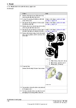
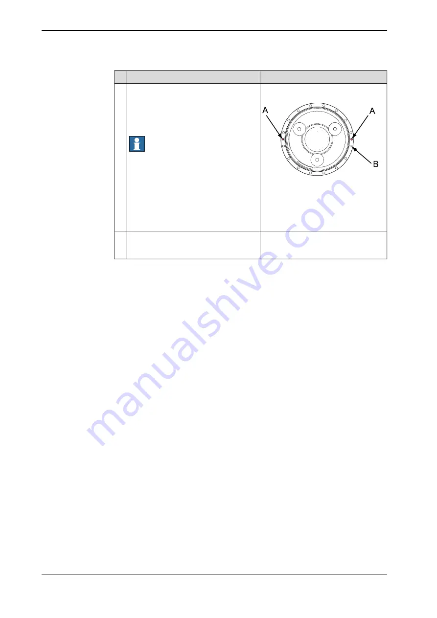
The figure below shows the gearbox, axis
1.
A Attachment holes for guide pins,
M12 in gearbox axis 1.
B Hole for attachment screw.
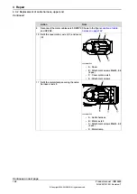
Fit two
guide pins
in the holes in the axis-1
gearbox, as shown in the figure to the right.
If using guide pins of different lengths, fit
the pin with maximal length of 130 mm on
the right side of the gearbox (seen from be-
hind).
Note
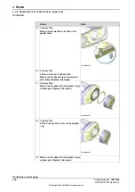
Lubricate the guide pins for easier fitting of
the arm system.
7
Lubricate the outer surface of the gearbox
for easier mating of the gearbox and arm
system.
8
Continues on next page
210
Product manual - IRB 6620
3HAC027151-001 Revision: T
© Copyright 2006-2018 ABB. All rights reserved.
4 Repair
4.3.3 Replacement of complete arm system
Continued
Summary of Contents for IRB 6620
Page 1: ...ROBOTICS Product manual IRB 6620 ...
Page 8: ...This page is intentionally left blank ...
Page 176: ...This page is intentionally left blank ...
Page 338: ...This page is intentionally left blank ...
Page 350: ...This page is intentionally left blank ...
Page 352: ...This page is intentionally left blank ...
Page 358: ......
Page 359: ......

