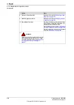
Note
Action
Art. no. is specified in
Required equipment on page 286
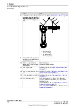
xx0600003099
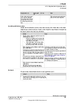
Fit the
lifting tool
on the upper
arm and secure the robot in an
overhead crane and lift it care-
fully up to its mounting posi-
tion.
8
•
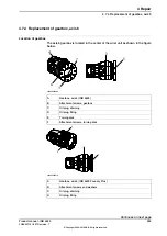
A : Lifting tool
•
B : Roundsling
•
C : Lifting chain
•
D : Hoisting block
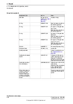
Use a crank in the gearbox in
order to find the holes for the
attachment screws.
9
M16x50 (16 pcs)
Refit the lower arm to the
gearbox axis 2 with its attach-
ment screws.
10
Tightening torque: 300 Nm.
Detailed in the section
Refit motor axis 2.
11
Detailed in the section
lower end (axes 1-2) on page 185
Refit the cable harness, axes
1-3.
12
Detailed in the section
Fill the gearbox axis 2 with oil.
13
Pendulum Calibration is described in
Operating
manual - Calibration Pendulum
, enclosed with the
calibration tools.
Recalibrate the robot.
14
Axis Calibration is described in
Calibration method on page 319
General calibration information is included in section
.
Continues on next page
292
Product manual - IRB 6620
3HAC027151-001 Revision: T
© Copyright 2006-2018 ABB. All rights reserved.
4 Repair
4.7.2 Replacement gearbox axis 2
Continued
Summary of Contents for IRB 6620
Page 1: ...ROBOTICS Product manual IRB 6620 ...
Page 8: ...This page is intentionally left blank ...
Page 176: ...This page is intentionally left blank ...
Page 338: ...This page is intentionally left blank ...
Page 350: ...This page is intentionally left blank ...
Page 352: ...This page is intentionally left blank ...
Page 358: ......
Page 359: ......


