4 Repair
4.6.6. Replacement of motor, axis 5, IRB 6640ID
3HAC026876-001 Revision: C
334
© Copyri
ght
200
6-2008 ABB.
All rights reserved.
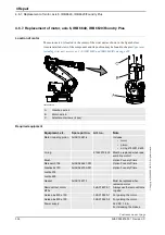
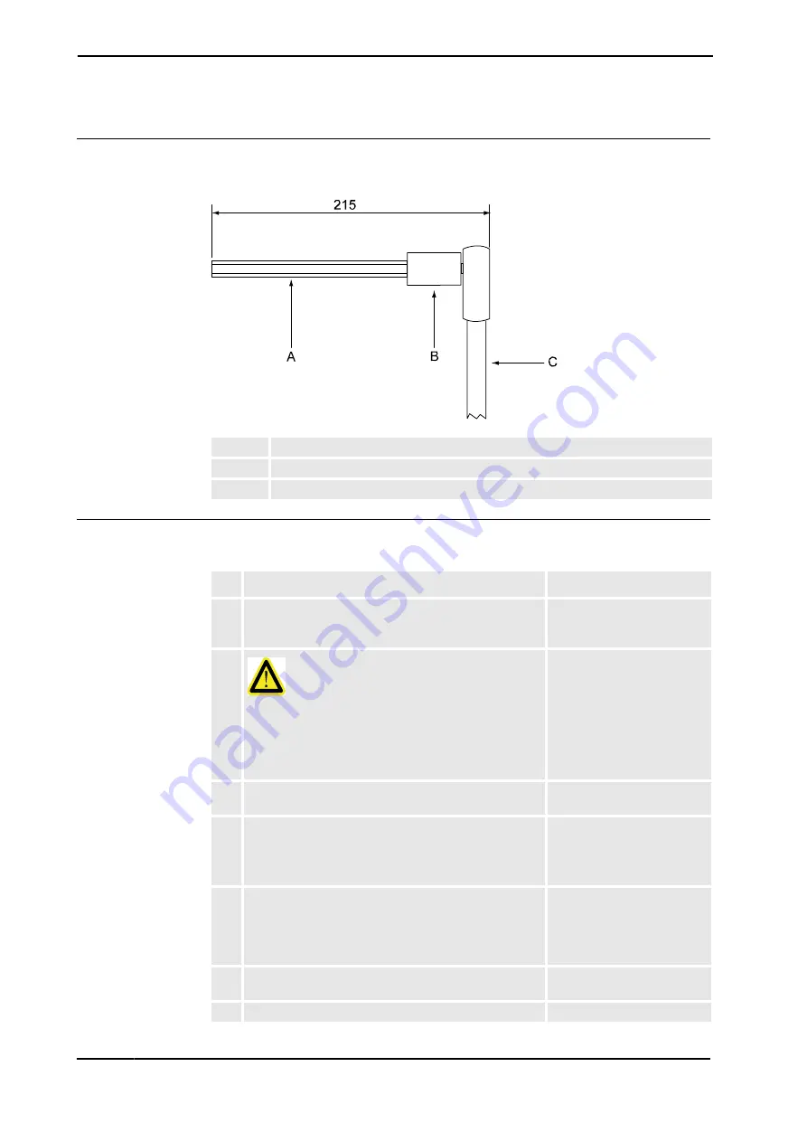
Removal tools, motor attachment screws
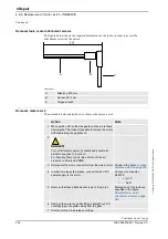
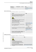
The figure below shows the required dimensions of the tools, in order to access the
attachment screws of the motor.
xx0500002271
Removal, motor axis 5
The procedure below details how to remove the motor, axis 5.
A
Allen key, Ø 6 mm
B
Socket, Ø 12 mm
C
Torque wrench
Action
Note
1. Move axis 4 +90º so that the gearbox of axis 5 is faced
downwards. This makes it possible to remove the motor
without draining the gearbox oil.
2.
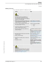
DANGER!
Turn off all electric power, hydraulic and pneumatic
pressure supplies to the robot!
For Foundry Prime robots: Do not turn off the air
pressure to motors and SMB.
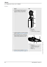
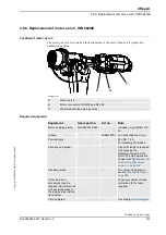
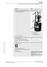
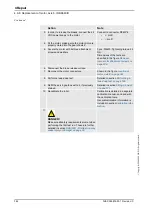
3. Disconnect the motor connectors from the axis 5 motor. Shown in the figure
4. In order to release the brakes, connect the 24 VDC
power supply to the motor.
Connect to connector
R3.MP5:
•
+ : pin C
•
- : pin D
5. Remove the three attachment screws of the motor.
Dimensions of the tools are
specified in the figure
Removal tools, motor
attachment screws on page
334
.
6. Remove the motor by gently lifting it straight out. Lift
carefully to get the pinion away from the gear.
7. Disconnect the brake release voltage.
Continued
Continues on next page


