4 Repair
4.7.2. Replacement of gearbox axis 2
3HAC020993-001 Revision: G
348
©
Co
py
rig
h
t 200
4-
200
8 ABB. All righ
ts reser
v
ed.
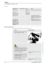
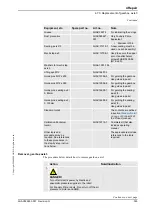
Removal, gearbox axis 2
The procedure below details how to remove the gearbox, axis 2.
Action
Note/Illustration
1.
DANGER!
Turn off all electric power, hydraulic and pneumatic
pressure supplies to the robot!
For Foundry Prime robots: Do not turn off the air
pressure to motors and SMB.
2. Secure the lower arm with the special fixture
equipment according to section
.
3. Unload the balancing device shaft by using the
press
tool, balancing device
, according to section
Unloading the balancing device on page 295
!
4. Drain the gearbox, axis 2.
Notice! Time-consuming activity!
Detailed in section
5. Remove the motor, axis 2.
Detailed in section
.
6. Remove the
rear attachment screws, gearbox
from
inside of the lower arm.
Shown in the figure
7. Remove the
cover, axis 2
by unscrewing its 14
attachment screws.
Shown in the figure
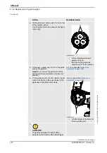
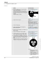
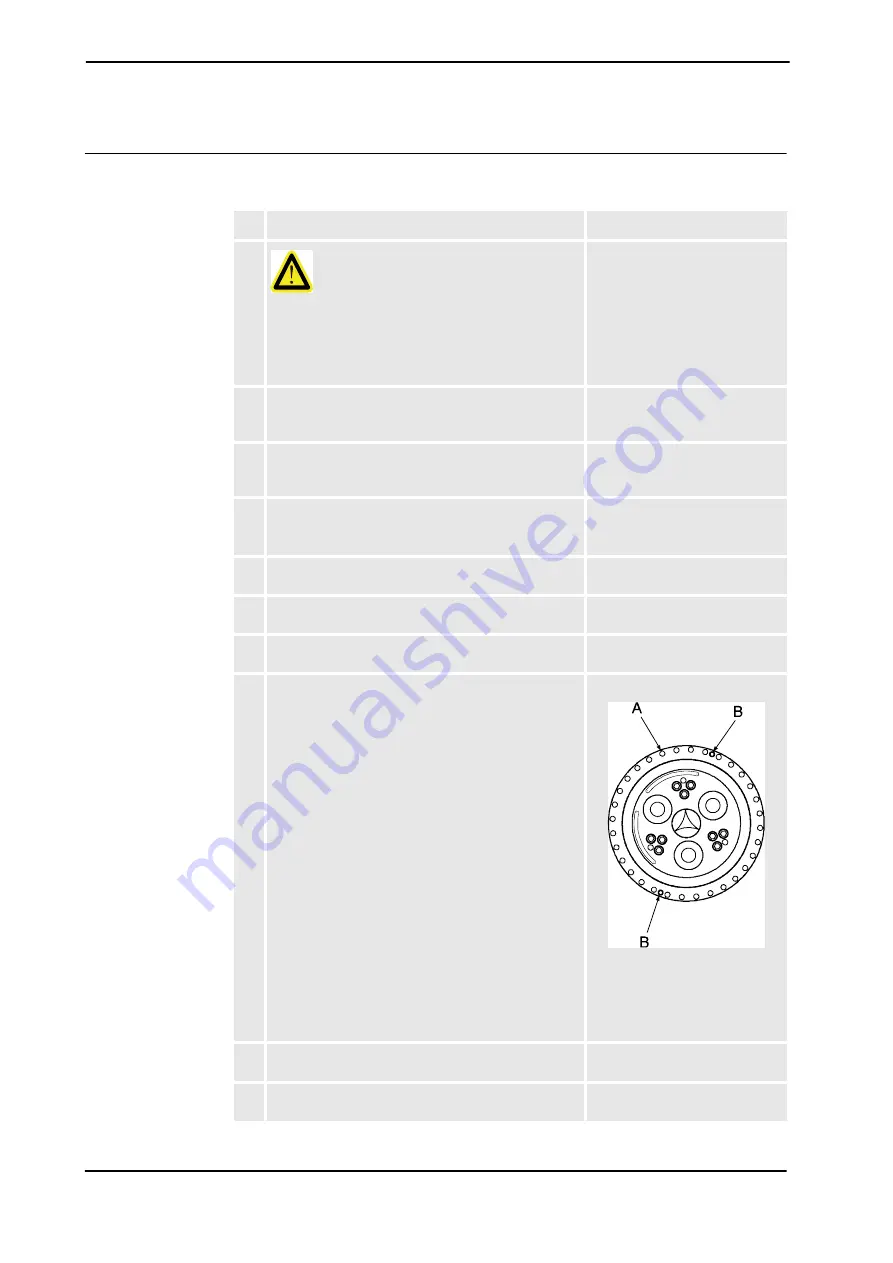
8. Remove the front attachment screws, gearbox,
shown in the figure to the right.
xx0300000550
•
A: Front attachment
screws, gearbox (32 pcs)
•
B: M12 holes for pressing
the gearbox out
9. Fit two
guide pins
in 180° relation to each other in the
empty holes of the front gearbox attachment screws.
10. If required, apply two M12 screws to the holes,
shown in the figure above, to press it free.
Continued
Continues on next page


