Note
Action
Art. no. is specified in
.
Apply the
lifting eye, M12
to the balancing device
and raise to unload the weight of the device.
5
Attachment is shown in the figure
Location of lower arm on page 273
Method 1 detailed in section
ing the balancing device using hy-
draulic press tool on page 313
Unload the balancing device in order to make the
piston rod and front ear adjustable when pulling
the front shaft out.
6
Shown in the figure
Remove the securing screw from the balancing
device
front shaft.
7
Art. no. is specified in
.
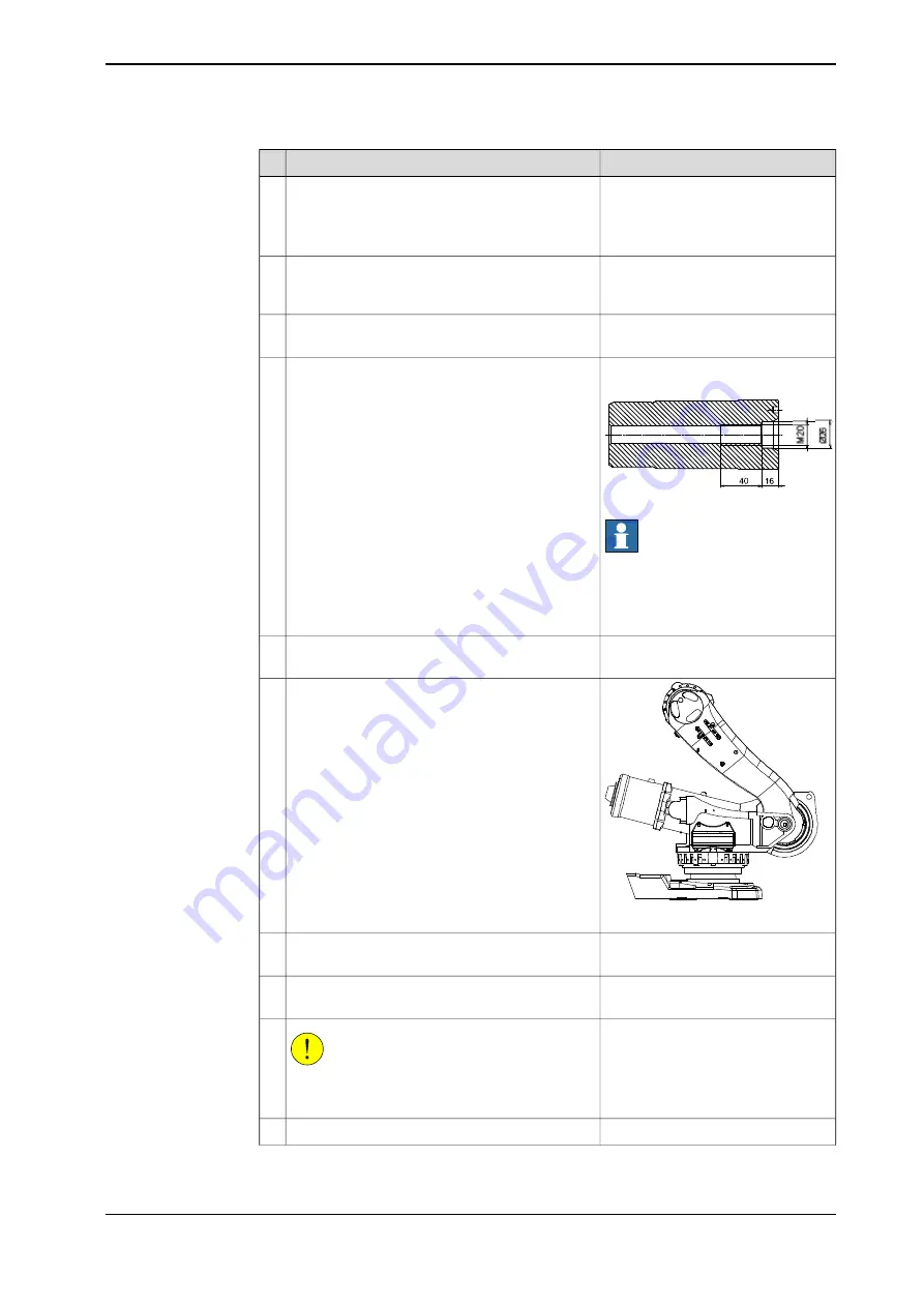
xx0300000060
Apply the
puller tool, balancing device shaft
to
the shaft of the balancing device, through the hole
in the frame.
The shaft has a M20 thread diameter, as shown
in the figure to the right.
Pull the shaft out using the puller tool and the
hydraulic pump.
8
Note
The dimension of the shaft puller tool
is M20. Do not mix up with the shaft
press tool used when mounting the
shaft.
Lower the balancing device until it rests safely
against the bottom of the frame.
9
xx0400001028
Move the lower arm backwards to the lowest po-
sition possible.
10
Art. no. is specified in
.
Apply the
lifting accessory
to the lower arm.
11
Detailed in section
.
Drain the oil from gearbox 2.
12
CAUTION
The lower arm weighs 160 kg! All lifting equip-
ment used must be sized accordingly!
13
Raise the tool to unload the lower arm.
14
Continues on next page
Product manual - IRB 6650S
279
3HAC020993-001 Revision: Z
© Copyright 2004-2018 ABB. All rights reserved.
4 Repair
4.4.4 Replacement of complete lower arm
Continued
Summary of Contents for IRB 6650S Series
Page 1: ...ROBOTICS Product manual IRB 6650S ...
Page 20: ...This page is intentionally left blank ...
Page 50: ...This page is intentionally left blank ...
Page 210: ...This page is intentionally left blank ...
Page 416: ...This page is intentionally left blank ...
Page 422: ...This page is intentionally left blank ...
Page 426: ...This page is intentionally left blank ...
Page 449: ......


