4 Repair
4.6.4. Replacement of motor, axis 5
3HAC028197-001 Revision: A
236
©
Co
py
rig
h
t 200
7-
200
8 ABB. All righ
ts reser
v
ed.
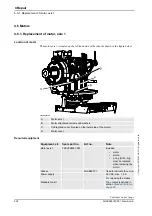
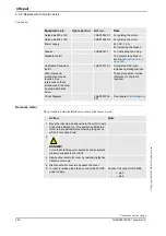
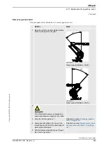
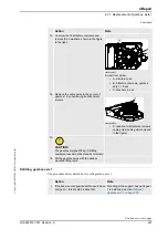
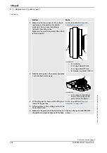
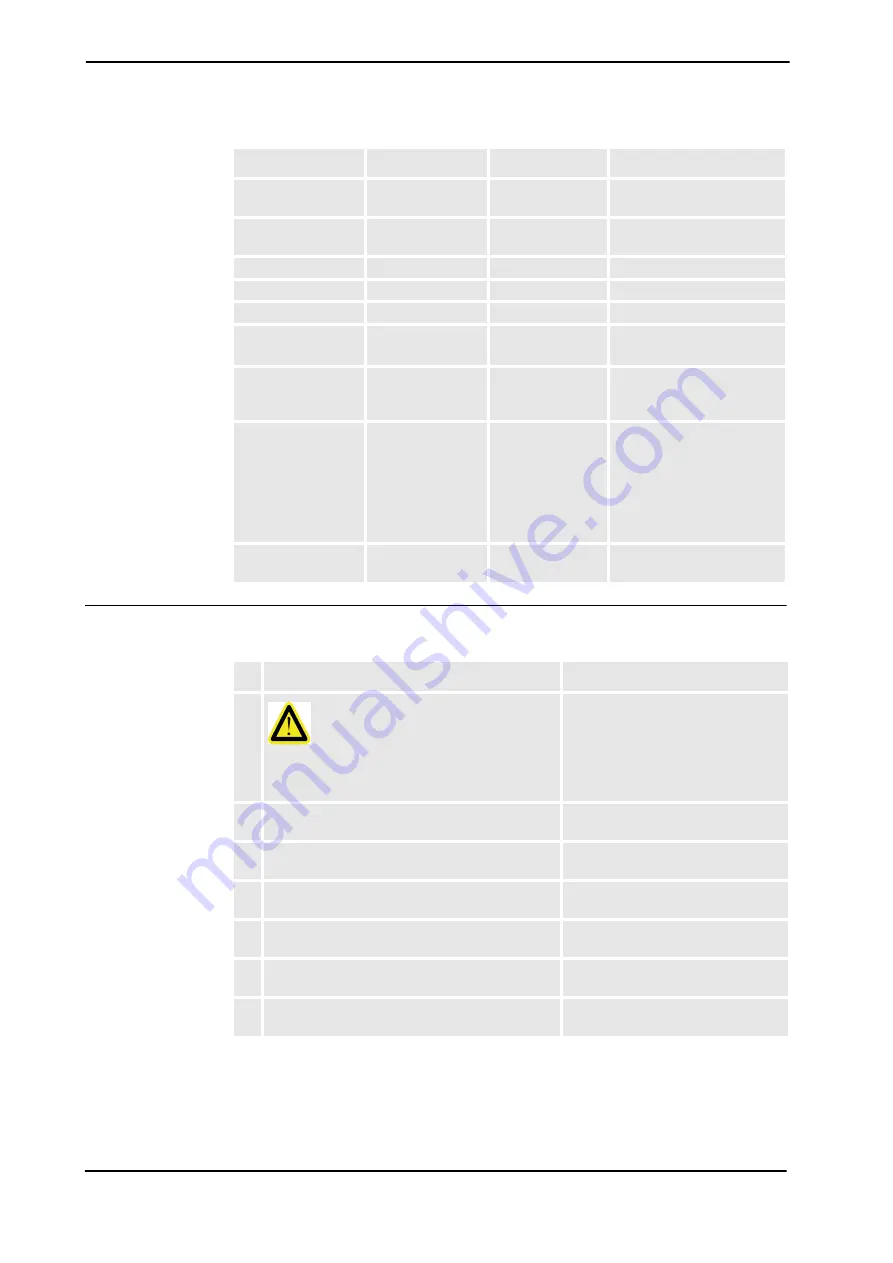
Removal, motor, axis 5
The procedure below details how to remove motor, axis 5.
Oil injector / max
500 MPa
3HAC021590-001
For pressing out the pinion,
motor 5.
Motor press pinion
3HAC021883-001
For pressing the pinion on to
the new motor.
Measuring tool
6896134-GN
Guide pins M8 x 100
3HAC15520-1
For guiding the motor.
Guide pins M8 x 150
3HAC15520-2
For guiding the motor.
Power supply
-
24 VDC, 1.5 A
For releasing the brakes.
Standard toolkit
-
The content is defined in
section
Other tools and
procedures may be
required. See
references to these
procedures in the
step-by-step instruc-
tions below.
These procedures include
references to the tools
required.
Circuit Diagram
3HAC025744-001
See chapter
Circuit
diagram
.
Equipment, etc.
Spare part no.
Art. no.
Note
Action
Note
1.
DANGER!
Turn off all electric power, hydraulic and
pneumatic pressure supplies to the robot!
2. Drain the oil from gearbox axis 5.
Detailed in section
.
3. Remove the wrist unit.
Detailed in section
4. Place the wrist unit safely on a workbench, in a
fixture or similar.
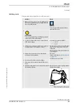
5. Remove the cover on top of the motor by
unscrewing its four attachment screws.
6. Remove the cable gland cover at the cable exit by
unscrewing its two attachment screws.
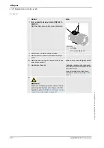
7. Disconnect all connectors beneath the motor
cover and remove the cable of the axis 5 motor.
Continued
Continues on next page
Summary of Contents for IRB 6660 - 130/3.1
Page 1: ...Product manual Articulated robot IRB 6660 130 3 1 IRB 6660 205 1 9 M2004 ...
Page 2: ......
Page 332: ... 0 1 23 3 4 5 5 6 2 70 2 888 2 9 6 0 9 9 2 A 8B C D 9 8 B ...
Page 333: ... 2 3 4 5 5 6 2 70 2 888 2 9 6 0 9 9 1 EF 2 888 2 9 6 9 9 8 B ...
Page 336: ... 98 2 888 7 066 0 10I 4 5 5 06 6 2 70 2 888 2 9 6 0 9 9 G E 7 F E 7 F 9 8 B ...
Page 347: ......

