4 Repair
4.7.1. Replacement of gearbox, axis 1
3HAC028197-001 Revision: A
248
©
Co
py
rig
h
t 200
7-
200
8 ABB. All righ
ts reser
v
ed.
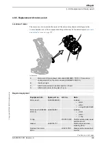
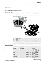
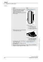
2. Make sure the two
o-rings
(C, D) on the cir-
cumference of the gearbox are seated
properly in their grooves respectively.
Lubricate them with
grease
.
Make sure the small o-ring around the oil hole
is fitted properly!
Art no. is specified in
.
xx0200000055
•
A: Guide pin
•
C: O-ring 3HAB 3772-54
•
D: O-ring 3HAB 3772-55
•
E: Sealing ring 3HAC 11581-4
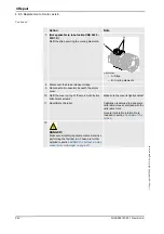
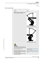
3. Refit the cable guide in the center of gearbox
1 with its attachment screws.
xx0200000256
•
A: Location for attachment
screws, cable guide (cable
guide removed in figure)
4. Fit the
lifting device, base
and the
lifting tool
(chain)
to the gearbox.
Art no. is specified in
.
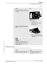
5. Lift the gearbox to its mounting position in the
center of the base.
6. Make sure the guide pin in the bottom face of
the gearbox is properly aligned with the base.
Shown in the figure xx0200000055
above!
Action
Note
Continued
Continues on next page
Summary of Contents for IRB 6660 - 130/3.1
Page 1: ...Product manual Articulated robot IRB 6660 130 3 1 IRB 6660 205 1 9 M2004 ...
Page 2: ......
Page 332: ... 0 1 23 3 4 5 5 6 2 70 2 888 2 9 6 0 9 9 2 A 8B C D 9 8 B ...
Page 333: ... 2 3 4 5 5 6 2 70 2 888 2 9 6 0 9 9 1 EF 2 888 2 9 6 9 9 8 B ...
Page 336: ... 98 2 888 7 066 0 10I 4 5 5 06 6 2 70 2 888 2 9 6 0 9 9 G E 7 F E 7 F 9 8 B ...
Page 347: ......


