4 Repair
4.7.3. Replacement of gearbox, axis 6
257
3HAC028197-001 Revision: A
©
Co
py
rig
h
t 200
7-
200
8 ABB. All righ
ts reser
v
ed.
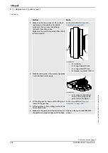
2. Make sure the
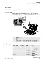
o-ring
is fitted to the rear of
the gearbox. Lubricate the o-ring with
grease.
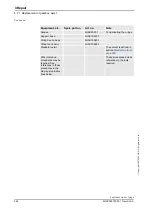
Art. no. is specified in
.
xx0100000132
•
A: O-ring, gearbox axis 6
3. Release the holding brake of motor axis 6. Detailed in section
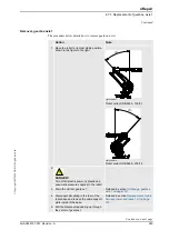
4. Insert the
gearbox, axis 6
into the wrist unit. Art. no. is specified in
.
Shown in the figure
Make sure the gears of the gearbox mate
with the gears of the motor!
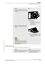
5. Secure the gearbox with the
attachment
screws and washers.
Shown in the figure
8 pcs : M8 x 40, 12.9 quality UNBRAKO,
Tightening torque: 30 Nm.
Reused screws may be used, providing
they are lubricated as detailed in section
before fitting.
6. Refit the
turning disk
.
Detailed in section
7. Perform a
leak-down test
.
Detailed in section
8. Refill the gearbox with oil.
Detailed in section
.
9. Recalibrate the robot.
Calibration is detailed in a separate
calibration manual, enclosed with the
calibration tools.
General calibration information is included
in section
Calibration information
.
Action
Note
Continued
Continues on next page
Summary of Contents for IRB 6660 - 130/3.1
Page 1: ...Product manual Articulated robot IRB 6660 130 3 1 IRB 6660 205 1 9 M2004 ...
Page 2: ......
Page 332: ... 0 1 23 3 4 5 5 6 2 70 2 888 2 9 6 0 9 9 2 A 8B C D 9 8 B ...
Page 333: ... 2 3 4 5 5 6 2 70 2 888 2 9 6 0 9 9 1 EF 2 888 2 9 6 9 9 8 B ...
Page 336: ... 98 2 888 7 066 0 10I 4 5 5 06 6 2 70 2 888 2 9 6 0 9 9 G E 7 F E 7 F 9 8 B ...
Page 347: ......

