2 Installation and commissioning
2.3.9. Installation of Chip protection - IRB 6660 - 205/1.9
3HAC028197-001 Revision: A
70
©
Co
py
rig
h
t 200
7-
200
8 ABB. All righ
ts reser
v
ed.
2.3.9. Installation of Chip protection - IRB 6660 - 205/1.9
NOTE!
This section is not applicable to the robot variant IRB 6660-130/3.1.
Location of Chip protection
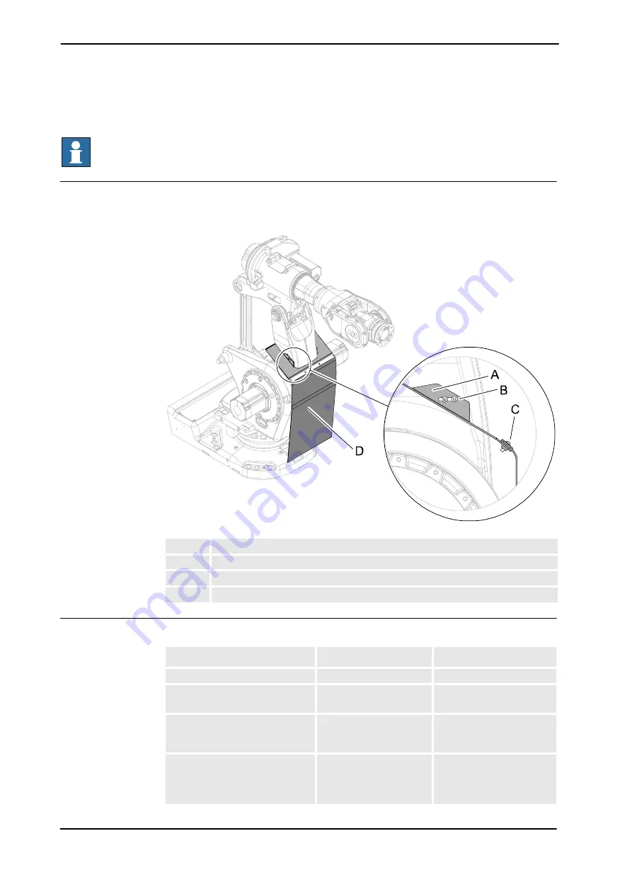
The chip protection is installed on the lower arm as shown in the figure below.
xx0700000630
Required equipment
A
Bracket
B
Attachment screws M6x16 quality 8.8-A2F (2 pcs per side)
C
Attachment screws M6x16 quality 8.8-A2F (4 pcs)
D
Protection
Equipment
Art. no.
Note
Chip protection
3HAC030124-001
Locking liquid
-
Loctite 243
For locking screws.
Standard toolkit
The content is defined in
section
.
Other tools and procedures may
be required. See references to
these procedures in the step-by-
step instructions below.
These procedures include
references to the tools
required.
Continues on next page
Summary of Contents for IRB 6660 - 130/3.1
Page 1: ...Product manual Articulated robot IRB 6660 130 3 1 IRB 6660 205 1 9 M2004 ...
Page 2: ......
Page 332: ... 0 1 23 3 4 5 5 6 2 70 2 888 2 9 6 0 9 9 2 A 8B C D 9 8 B ...
Page 333: ... 2 3 4 5 5 6 2 70 2 888 2 9 6 0 9 9 1 EF 2 888 2 9 6 9 9 8 B ...
Page 336: ... 98 2 888 7 066 0 10I 4 5 5 06 6 2 70 2 888 2 9 6 0 9 9 G E 7 F E 7 F 9 8 B ...
Page 347: ......


