4 Repair
4.4.3. Replacement of upper arm
3HAC028197-001 Revision: A
192
©
Co
py
rig
h
t 200
7-
200
8 ABB. All righ
ts reser
v
ed.
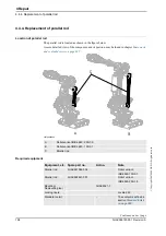
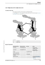
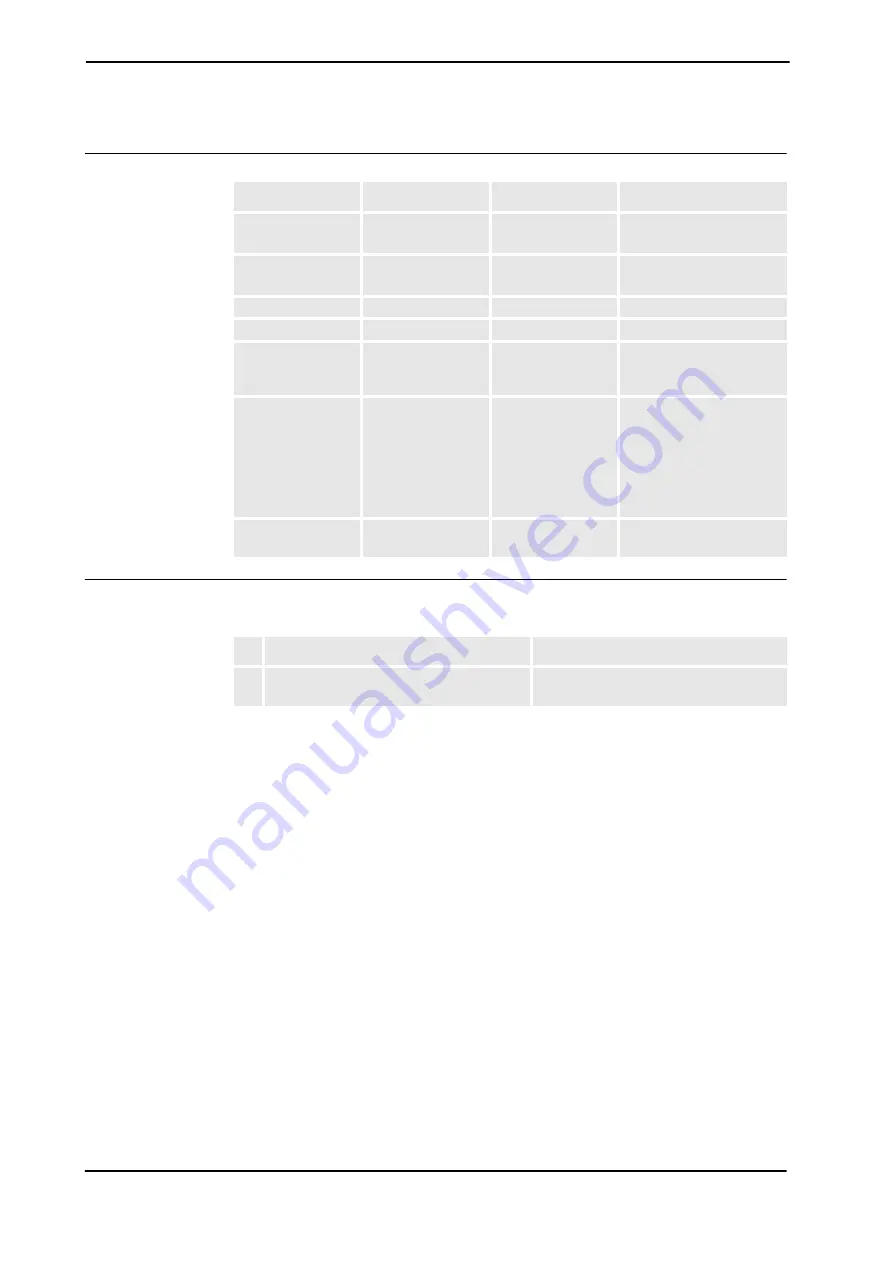
Required equipment
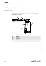
Removal, upper arm
The procedure below details how to remove the upper arm.
Equipment, etc.
Spare part no.
Art.no.
Note
Upper arm, axis 4
3HAC026674-001
Robot variant:
IRB 6660-130/3.1
Upper arm, axis 4
3HAC029161-001
Robot variant:
IRB 6660-205/1.9
Grease filling tool
-
KM12 socket
3HAC5347-1
Standard toolkit
-
The content is defined in
section
Other tools and
procedures may be
required. See
references to these
procedures in the
step-by-step
instructions below.
These procedures include
references to the tools
required.
Circuit diagram
3HAC025744-001
See chapter
Circuit
diagram
.
Action
Note
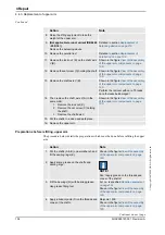
1. Remove all equipment fitted to the turning
disk.
Continued
Continues on next page
Summary of Contents for IRB 6660 - 130/3.1
Page 1: ...Product manual Articulated robot IRB 6660 130 3 1 IRB 6660 205 1 9 M2004 ...
Page 2: ......
Page 332: ... 0 1 23 3 4 5 5 6 2 70 2 888 2 9 6 0 9 9 2 A 8B C D 9 8 B ...
Page 333: ... 2 3 4 5 5 6 2 70 2 888 2 9 6 0 9 9 1 EF 2 888 2 9 6 9 9 8 B ...
Page 336: ... 98 2 888 7 066 0 10I 4 5 5 06 6 2 70 2 888 2 9 6 0 9 9 G E 7 F E 7 F 9 8 B ...
Page 347: ......


