4 Repair
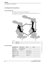
4.5.3. Replacement of balancing device
219
3HAC028197-001 Revision: A
©
Co
py
rig
h
t 200
7-
200
8 ABB. All righ
ts reser
v
ed.
Removal
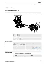
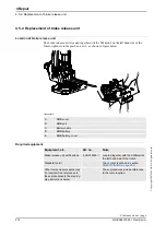
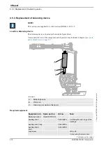
The procedure below details how to remove the balancing device.
Screw
M12 x 50
For neutralizing the spring force
of the balancing cylinder.
Lubrication tool
3HAC5222-2
Standard toolkit
-
The content is defined in section
Other tools and
procedures may be
required. See
references to these
procedures in the
step-by-step
instructions below.
These procedures include
references to the tools required.
Equipment, etc.
Spare part no.
Art.no.
Note
Action
Note
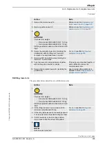
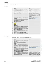
1. Move the robot to a position close enough to its
calibration position, to allow the lock screw to
be inserted into the hole for the lock screw.
The balancing device must be placed
in a 90° angle from the floor, in order
the be lifted in the most secure way.
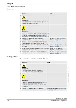
2. Lock the lower arm by inserting the lock screw
into the hole.
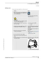
xx0600002736
•
A: Hole for lock screw M16x90
3.
DANGER!
Turn off all electric power, hydraulic and
pneumatic pressure supplies to the robot!
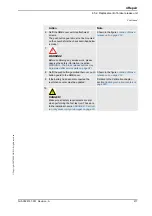
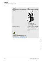
4. Remove the protection hood in the upper end of
the balancing device.
Continued
Continues on next page
Summary of Contents for IRB 6660 - 130/3.1
Page 1: ...Product manual Articulated robot IRB 6660 130 3 1 IRB 6660 205 1 9 M2004 ...
Page 2: ......
Page 332: ... 0 1 23 3 4 5 5 6 2 70 2 888 2 9 6 0 9 9 2 A 8B C D 9 8 B ...
Page 333: ... 2 3 4 5 5 6 2 70 2 888 2 9 6 0 9 9 1 EF 2 888 2 9 6 9 9 8 B ...
Page 336: ... 98 2 888 7 066 0 10I 4 5 5 06 6 2 70 2 888 2 9 6 0 9 9 G E 7 F E 7 F 9 8 B ...
Page 347: ......

