4 Repair
4.6.2. Replacement of motor, axes 2 and 3
227
3HAC028197-001 Revision: A
©
Co
py
rig
h
t 200
7-
200
8 ABB. All righ
ts reser
v
ed.
4.6.2. Replacement of motor, axes 2 and 3
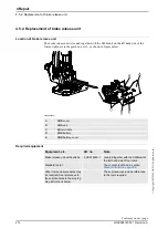
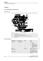
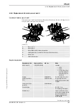
Location of motors, axes 2 and 3
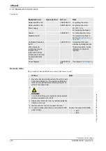
The motors axes 2 and 3 are located on either side of the robot as shown in the figure below.
The procedure is the same for both motors.
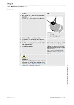
xx0600002599
Required equipment
A
Motor, axis 2
B
Motor, axis 3
C
Motor attachment screws and washers
D
Cable gland cover (located on the lower side of the motor)
E
Motor cover
F
Hole for lock screw
Equipment, etc.
Spare part no.
Art. no.
Note
Motor axis 2-3
3HAC021030-001
Includes
•
motor
•
pinion
•
o-ring (The o-ring
must be replaced
when the motor is
replaced)
Grease
3HAB3537-1
For lubricating the o-ring.
Guide pins M10 x
150
3HAC13120-2
For guiding the motor.
Guide pins are to be used
in pairs!
Lifting tool, motor
axes 2-3
3HAC14586-1
Power supply
-
24 VDC, 1.5 A
For releasing the brakes.
Rotation tool
Used to rotate the motor
pinion when mating it to the
gear, when brakes are
released with 24 VDC
power supply.
Continues on next page
Summary of Contents for IRB 6660 - 130/3.1
Page 1: ...Product manual Articulated robot IRB 6660 130 3 1 IRB 6660 205 1 9 M2004 ...
Page 2: ......
Page 332: ... 0 1 23 3 4 5 5 6 2 70 2 888 2 9 6 0 9 9 2 A 8B C D 9 8 B ...
Page 333: ... 2 3 4 5 5 6 2 70 2 888 2 9 6 0 9 9 1 EF 2 888 2 9 6 9 9 8 B ...
Page 336: ... 98 2 888 7 066 0 10I 4 5 5 06 6 2 70 2 888 2 9 6 0 9 9 G E 7 F E 7 F 9 8 B ...
Page 347: ......


