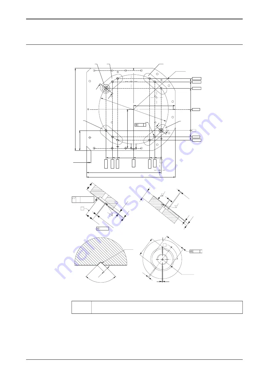
Base plate drawing
The following figure shows the option base plate (dimensions in mm).
A
A
B
B
C
D
G
H
E
F
2x R525
598,31
560,85
487,01
243,5
0
73,84
111,30
1020
857,3
7
3
,8
4
1
3
2
,6
4
3
1
7
,3
5
0
2
,0
4
5
6
0
,8
5
6
3
4
,6
8
0
2x 50x45º
2
3
1
,5
2
x
4
5
0
9
5
0
(Ø 80
0)
12x M24
Ø1 A
455
C
A
4x4
8
13
(2
)
1
,6
3x4
5º
0.3
Ø 45P7
A-A
Ø1.5
(4x)
6,3
(4
8)
(2
)
1,6
3x4
5º
B-B
(2
)
13
3x R1
3x4
3x 90º
C-C
45
K
7
+0
,5
0
47
0,25 c
(2x R22,5)
1,6
D
(2
)
c
5
2
,5º
Common Zone
E, F, G, H
xx1000001053
Common tolerance zone (accuracy all over the base plate from one contact
surface to the other)
E, F, G, H
Continues on next page
22
Product specification - IRB 6660
3HAC087212-001 Revision: A
© Copyright 2004-2023 ABB. All rights reserved.
1 Description
1.3.3 Mounting the manipulator
Continued
Summary of Contents for IRB 6660
Page 1: ...ROBOTICS Product specification IRB 6660...
Page 6: ...This page is intentionally left blank...
Page 8: ...This page is intentionally left blank...
Page 60: ...This page is intentionally left blank...
Page 74: ......
Page 75: ......


