Note
Action
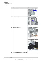
Connect the 24 VDC power supply to release the
brakes.
4
Connect to R2.MP1-connector:
•
+ = pin 2
•
- = pin 5
Note
Put the cables to the brake release tool through
the hole in the tool shelf.
Guide pin, M10x150: 3HAC15521-
2
Fit guide pins in opposite holes.
5
Always use guide pins in pairs.
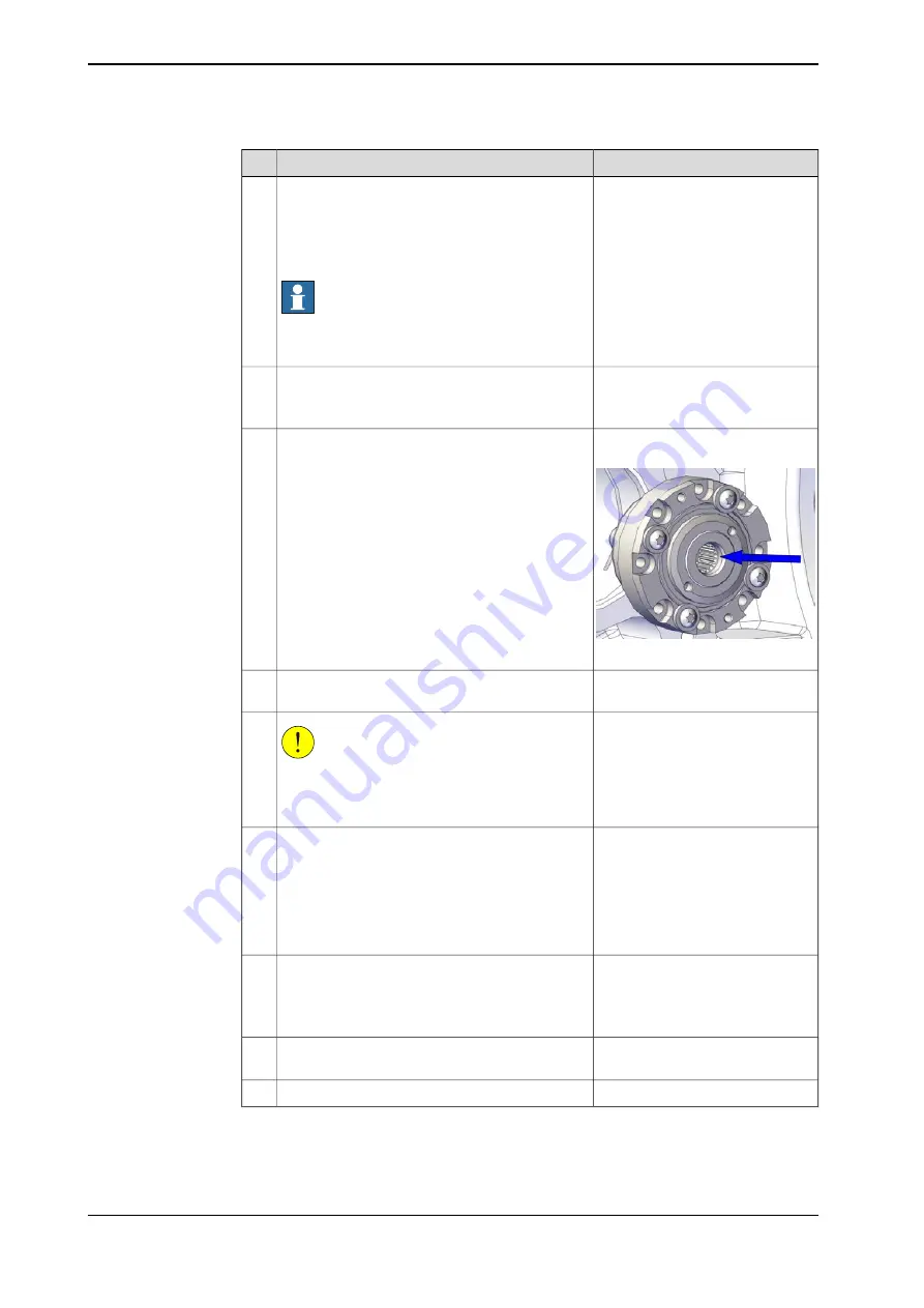
Grease: Castrol Molub. Alloy 777-
1 NG
xx1500002346
Apply 3 gram grease on the splines before fitting.
6
Put the motor on the tool shelf and rotate it into
position.
7
CAUTION
Whenever parting/mating motor pinion and hub,
the splines may be damaged if excessive force is
used.
8
Raise the revolving handle to assemble motor.
•
Make sure that the motor pinion is properly
mated into the hub.
•
Make sure that the motor pinion does not
get damaged.
•
Make sure that the direction of the cable
exit is facing the correct way.
9
Bits extender: 3HAC12342-1
Secure the motor with its attachment screws and
washers.
10
Tightening torque: 50 Nm.
Use a bits extender to reach the screws.
Screw dimension : M10x40 quality
12.9 Gleitmo (4 pcs)
See
.
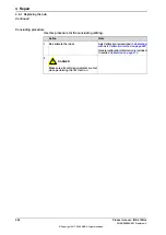
Perform a leak-down test (if not already done).
11
Disconnect the 24 VDC power supply.
12
Continues on next page
550
Product manual - IRB 6700Inv
3HAC058254-001 Revision: L
© Copyright 2017 - 2020 ABB. All rights reserved.
4 Repair
4.8.1 Replacing the hub
Continued
Summary of Contents for IRB 6700Inv
Page 1: ...ROBOTICS Product manual IRB 6700Inv ...
Page 16: ...This page is intentionally left blank ...
Page 40: ...This page is intentionally left blank ...
Page 182: ...This page is intentionally left blank ...
Page 672: ...This page is intentionally left blank ...
Page 704: ...This page is intentionally left blank ...
Page 720: ...This page is intentionally left blank ...
Page 722: ...This page is intentionally left blank ...
Page 729: ......


