Note
Action
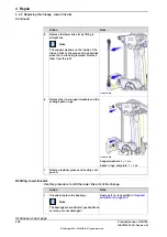
Apply the
shaft fitting
/
removing tool (part
3HAC038174-021)
.
Note
For information how to use the tool, please
contact ABB.
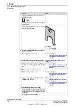
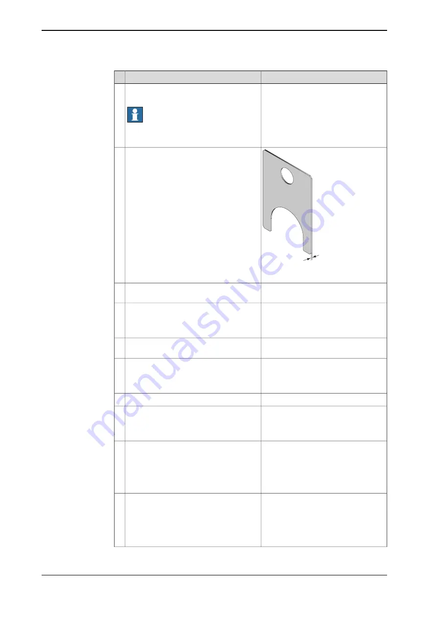
6
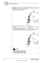
A
xx1100000030
•
A: T=2.5 mm
Put the
shims
between the upper and lower
arms on the axis 3 side.
7
Press the parts together using the
shaft fit-
ting
/
removing tool
.
8
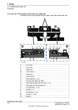
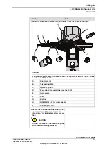
Shown in the figure:
•
Cut away view of the assembly of
the upper arm components on
page 212
Fit
o-ring
on the
sealing ring
.
9
Specified in
.
Lubricate the bearing with
bearing grease
.
10
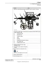
Shown in the figure:
•
Cut away view of the assembly of
the upper arm components on
page 212
Fit the
sealing ring
with the o-ring fitted, in
the lower arm, using a plastic mallet or simil-
ar.
11
Wipe the lock nut clean from grease.
12
Shown in the figure:
•
Cut away view of the assembly of
the upper arm components on
page 212
Fit the
sealing
on the lock nut.
13
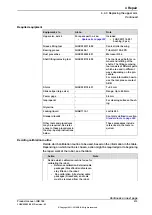
For art. no. see:
•
Required equipment on page 213
Shown in the figure:
•
Cut away view of the assembly of
the upper arm components on
page 212
Apply
locking liquid
(
Loctite 243
) on the
threads of the lock nut.
14
Only applicable to the axis 3 side!
15
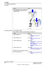
Secure all parts with the lock nut (flat side
facing inwards), using s
leeve KM nut type 15
(3HAC038174-024)
with a tightening torque
of
175 Nm
.
Let the shims remain mounted.
Continues on next page
224
Product manual - IRB 760
3HAC039838-001 Revision: M
© Copyright 2011-2018 ABB. All rights reserved.
4 Repair
4.4.3 Replacing the upper arm
Continued
Summary of Contents for IRB 760 Series
Page 1: ...ROBOTICS Product manual IRB 760 ...
Page 8: ...This page is intentionally left blank ...
Page 46: ...This page is intentionally left blank ...
Page 96: ...This page is intentionally left blank ...
Page 144: ...This page is intentionally left blank ...
Page 394: ...This page is intentionally left blank ...
Page 400: ......
Page 401: ......


