3.3.8 Fitting equipment on the robot (robot dimensions)
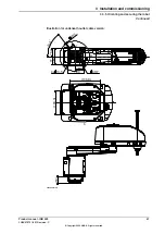
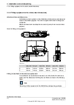
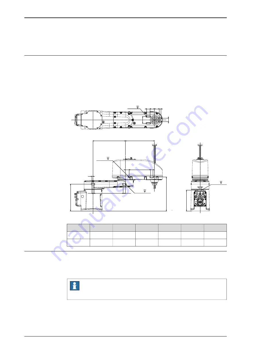
Attachment holes and dimensions
Extra loads can be mounted on robot. Definitions of dimensions and masses are
shown in the following figures. The robot is supplied with holes for fitting extra
equipment.
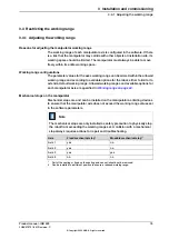
Maximum allowed arm load depends on center of gravity of arm load and robot
payload.
Holes for fitting extra equipment
X
10
33
260
3
0
3
20
Y
8xM5 10
192
20
2
4
0
.5
20
43
40
30
3
0
6
0
15
8xM4 8
20
1
8
5
2xM6 12
6xM4 8
xx2000001149
0.65_0.3
0.65_0.18
0.55_0.3
0.55_0.18
0.45_0.3
0.45_0.18
390 mm
390 mm
290 mm
290 mm
190 mm
190 mm
X
360 mm
360 mm
260 mm
260 mm
160 mm
160 mm
Y
Fitting of end effector to the ball screw spline shaft
An end effector can be attached to the lower end of the shaft of the ball screw
spline unit. The dimensions for fitting the end effector is shown in the following
figure.
Note
Mounting of other equipment on the IRB 920 may damage the gearboxes.
Continues on next page
72
Product manual - IRB 920
3HAC075721-001 Revision: C
© Copyright 2022 ABB. All rights reserved.
3 Installation and commissioning
3.3.8 Fitting equipment on the robot (robot dimensions)
Summary of Contents for IRB 920
Page 1: ...ROBOTICS Product manual IRB 920 ...
Page 8: ...This page is intentionally left blank ...
Page 14: ...This page is intentionally left blank ...
Page 50: ...This page is intentionally left blank ...
Page 110: ...This page is intentionally left blank ...
Page 984: ...This page is intentionally left blank ...
Page 1000: ...This page is intentionally left blank ...
Page 1002: ...This page is intentionally left blank ...
Page 1006: ......
Page 1007: ......


