4 Repair
4.2.2 Changing the gearbox
76
3HAC026320-001 Revision: A
To assemble
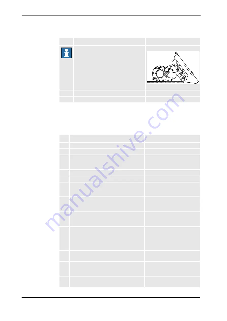
NOTE!
Make sure that the foot is stable
Figure 19:
9.
Undo screws.
See foldout/pos. <1/4>.
10.
Separate the base from the gear unit.
Action
Note /Illustration
Action
Note/Illustration
1.
Place a new gear unit on the table.
2.
Raise the base.
3.
Screw in the screws together with their washers. See foldout/pos. <1/4> and <1/3>.
Tighten using a torque of 68 Nm
±10%.
4.
Replace the bottom plate using screws.
See foldout/pos. <1/5> and <1/7>
5.
Turn the foot.
6.
Replace the lower arm.
Described in section:
Dismantling the lower arm on page
82
.
7.
Replace the parallel arm.
Described in section:
Dismantling the parallel arm on
page 89
8.
Replace the upper arm.
Described in section:
Dismantling the complete upper
arm on page 92
9.
Replace the cabling.
Described in section:
Changing the cabling in axes 1, 2
and 3 on page 103
Changing serial measuring boards
on page 102
.
10.
Replace the tie rod.
Described in section:
Changing the tie rod on page 90
11.
Replace the balancingd springs.
Described in section:
Dismantling the balancing springs
on page 85
12.
Calibrate the robot.
Described in section:
Summary of Contents for IRB1410
Page 1: ...Product manual Articulated robot IRB1410 M2004 ...
Page 2: ......
Page 3: ...Product manual IRB 1410 M2004 ID 3HAC026320 001 Revision A ...
Page 8: ...Table of Contents 6 ...
Page 114: ...4 Repair 4 8 1 General 112 3HAC026320 001 Revision A ...
Page 124: ......
Page 136: ......
Page 138: ...7 Recommended Spare parts 7 0 1 Spare parts 136 Revision A 3HAC026320 001 ...
Page 140: ...8 Foldouts 8 0 1 Introduction 138 3HAC026320 001 Revision A ...
Page 141: ......
Page 142: ......
Page 143: ......
Page 144: ......
Page 145: ......
Page 146: ......
Page 147: ......
Page 148: ......
Page 149: ......
Page 150: ......
Page 164: ...Index 152 3HAC026320 001 ...
Page 165: ......


