2 Installation and commissioning
2.2.2 Connection of Extra Equipment to the Manipulator
52
3HAC026320-001 Revision: A
2.2.2 Connection of Extra Equipment to the Manipulator
Technical data for customer connections.
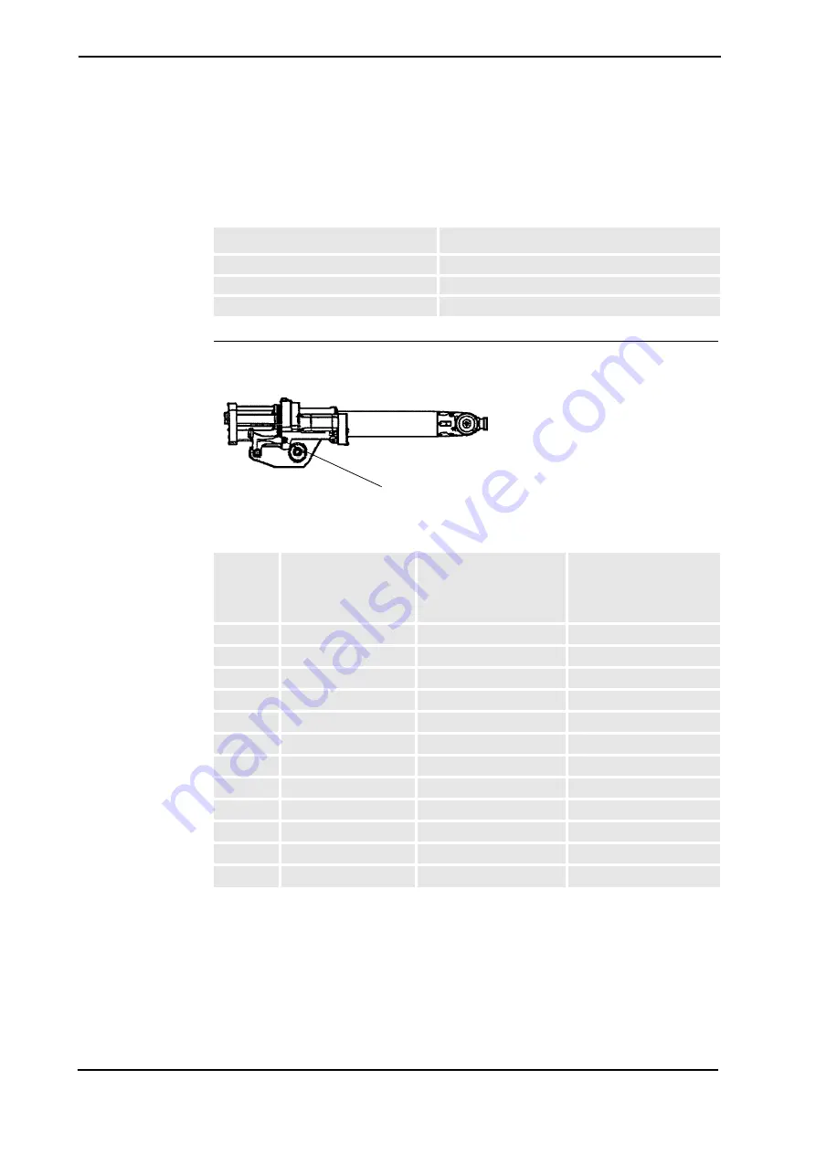
Connections on Upper Arm
Figure 15: Customer Connections on Upper Arm.
Signals
Conductor resistance
< 3 ohm, 0.154 mm
2
Max. voltage
50 V AC/DC
Max. current
250 mA
Signal
Name
Customer Terminal
Controller (optional)
Customer Contact
on Upper Arm, R2
Customer Contact on
Manipulator Base
(Cable not supplied)
CSA
XT5.1
R2.CS.A
R1.CS.A
CSB
XT5.2
R2.CS.B
R1.CS.B
CSC
XT5.3
R2.CS.C
R1.CS.C
CSD
XT5.4
R2.CS.D
R1.CS.D
CSE
XT5.5
R2.CS.E
R1.CS.E
CSF
XT5.6
R2.CS.F
R1.CS.F
CSG
XT5.7
R2.CS.G
R1.CS.G
CSH
XT5.8
R2.CS.H
R1.CS.H
CSJ
XT5.9
R2.CS.J
R1.CS.J
CSK
XT5.10
R2.CS.K
R1.CS.K
CSL
XT5.11
R2.CS.L
R1.CS.L
CSM
XT5.12
R2.CS.M
R1.CS.M
R2.CS
Summary of Contents for IRB1410
Page 1: ...Product manual Articulated robot IRB1410 M2004 ...
Page 2: ......
Page 3: ...Product manual IRB 1410 M2004 ID 3HAC026320 001 Revision A ...
Page 8: ...Table of Contents 6 ...
Page 114: ...4 Repair 4 8 1 General 112 3HAC026320 001 Revision A ...
Page 124: ......
Page 136: ......
Page 138: ...7 Recommended Spare parts 7 0 1 Spare parts 136 Revision A 3HAC026320 001 ...
Page 140: ...8 Foldouts 8 0 1 Introduction 138 3HAC026320 001 Revision A ...
Page 141: ......
Page 142: ......
Page 143: ......
Page 144: ......
Page 145: ......
Page 146: ......
Page 147: ......
Page 148: ......
Page 149: ......
Page 150: ......
Page 164: ...Index 152 3HAC026320 001 ...
Page 165: ......


