Disassembly/Assembly
Guidelines
IRB 6400
Page 11 - 16
Robot Calibration
Precision Resolver Calibration Procedure (Cont)
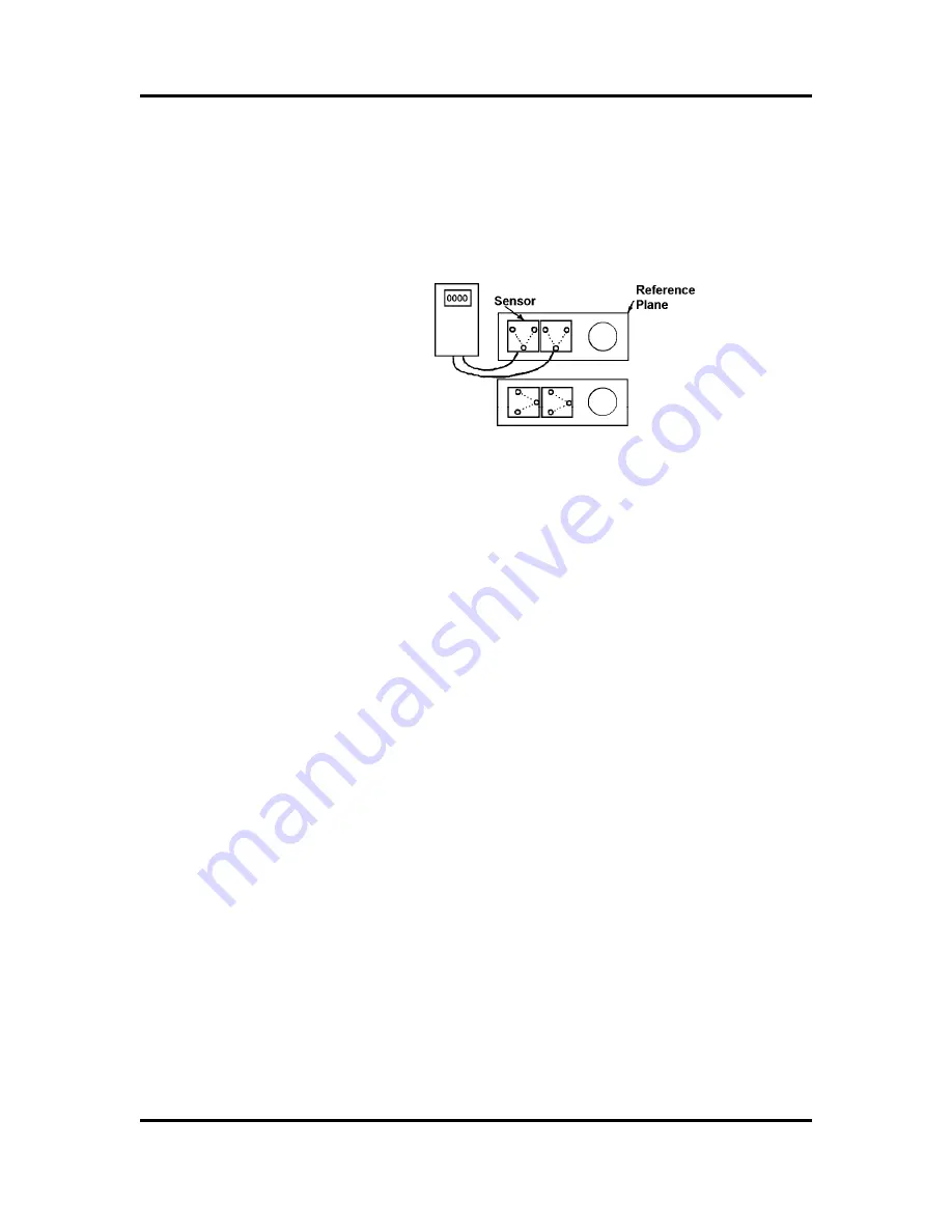
Calibrate the sensors against each other using a
reference plane surface in the same direction. The
sensors must be calibrated every time they are
used for a new direction.
Figure 2 - Calibrating the Sensors
Calibrating Axis 2-6
7.
Release the enabling device.
8.
Mount sensor fixture (6896 0011-GM) on the base
reference plane.
9.
Mount elbow fixture (6896 0011-LP) on the lower
arm calibration plane.
10. Mount sensor fixture (6808 0011-GM) on the wrist
calibration plane turned upwards.
11. Mount intermediate plate (6896 134-GZ) on the
turn disc. Mount elbow fixture (6808 0011-GU) on
the intermediate plate. Note that the elbow fixture
position is adjusted with a guide pin.
12. Mount inclination instrument (6807 081-D). One
sensor is to be mounted on the reference plane and
the other on the elbow fixture for Axis 2. Both
sensors are to be positioned in the same direction.
See also Figure 3.
NOTE
: The sensor unit must always be mounted on
top of the fixture.
Summary of Contents for IRB6400
Page 5: ...Disassembly Assembly Guidelines IRB 6400 Introduction SECTION 1 ...
Page 15: ...Disassembly Assembly Guidelines IRB 6400 Safety SECTION 2 ...
Page 26: ...Disassembly Assembly Guidelines IRB 6400 Robot Handling SECTION 3 ...
Page 34: ...Disassembly Assembly Guidelines IRB 6400 Maintenance SECTION 4 ...
Page 61: ...Disassembly Assembly Guidelines IRB 6400 Axis 1 SECTION 5 Disassembly Assembly ...
Page 81: ...Disassembly Assembly Guidelines IRB 6400 Axes 2 3 SECTION 6 Disassembly Assembly ...
Page 107: ...Disassembly Assembly Guidelines IRB 6400 Axis 4 SECTION 7 Disassembly Assembly ...
Page 131: ...Disassembly Assembly Guidelines IRB 6400 Axis 5 SECTION 8 Disassembly Assembly ...
Page 143: ...Disassembly Assembly Guidelines IRB 6400 Axis 6 SECTION 9 Disassembly Assembly ...
Page 152: ...Disassembly Assembly Guidelines IRB 6400 Cables Guidelines SECTION 10 ...
Page 169: ...Disassembly Assembly Guidelines IRB 6400 Robot Calibration SECTION 11 ...
Page 171: ...Disassembly Assembly Guidelines IRB6400 Page 11 2 RobotCalibration NOTES ...
Page 196: ...Page 11 27 RobotCalibration Disassembly Assembly Guidelines IRB6400 NOTES ...
Page 197: ...Disassembly Assembly Guidelines IRB6400 Page 11 28 RobotCalibration NOTES ...
Page 198: ...Disassembly Assembly Guidelines IRB 6400 Parts Lists Illustrations SECTION 12 ...
Page 209: ...Disassembly Assembly Guidelines IRB 6400 Reference SECTION 13 Mechanical Layouts ...
Page 211: ...Disassembly Assembly Guidelines IRB 6400 Reference SECTION 14 Cable Layouts ...


