Disassembly/Assembly
Guidelines
IRB 6400
Robot Handling
Page 3- 6
RESTRICTING AXES MOVEMENT MECHANICALL Y
When installing the manipulator, make sure that it can move freely within its e n-
tire working space. If there is a risk that it may collide with other objects, its
working space should be limited, both mechanically and using software. Insta l-
lation of an optional extra stop for the main axes 1, 2 and 3 is described belo w
.
Limiting the working space using software is described in the System Para m-
eters in the User’s Guide.
Axis 1
The range of rotation for axis 1 can be limited mechanically by fitting extra m e-
chanical stop arms (3HAB 4224-001). Instructions for doing this are supplied
with the kit.
CAUTION: THE MECHANICAL STOP PIN AND THE EXTRA MOV-
ABLE MECHANICAL STOP ARM FOR AXIS 1 BE REPLACED AF-
TER ANY HARD COLLISION TYPE STOP, IF THE PIN OR ARM
HAS BEEN BENT OR DAMAGED IN ANY WAY.
Axes 2 and 3
The working range of axes 2 and 3 is limited by mechanically stops and can be
reduced by adding fixed mechanical stops (3HAB 4087-001). The stops are
mounted on the inside of the frame to each axis. Extra stops must be mounted
in a row, with starting-point from the fixed stop .
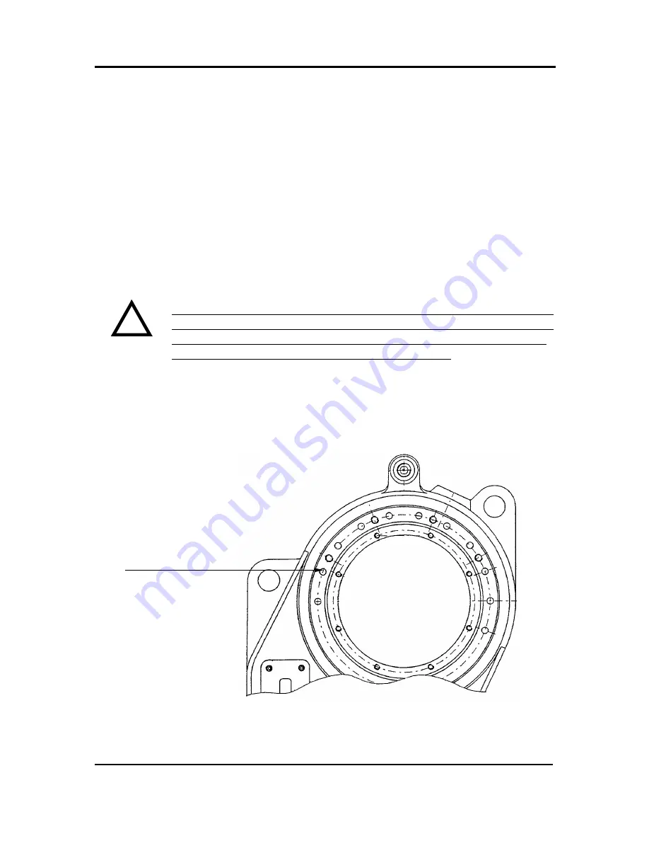
Figure 8 Mechanically limiting axes 2 and 3.
Holes for extra stop s
FOR AXES 1-3 IS 3HAB 4225-001
.
MECHANICAL STOPS PART NUMBER
C
Summary of Contents for IRB6400
Page 5: ...Disassembly Assembly Guidelines IRB 6400 Introduction SECTION 1 ...
Page 15: ...Disassembly Assembly Guidelines IRB 6400 Safety SECTION 2 ...
Page 26: ...Disassembly Assembly Guidelines IRB 6400 Robot Handling SECTION 3 ...
Page 34: ...Disassembly Assembly Guidelines IRB 6400 Maintenance SECTION 4 ...
Page 61: ...Disassembly Assembly Guidelines IRB 6400 Axis 1 SECTION 5 Disassembly Assembly ...
Page 81: ...Disassembly Assembly Guidelines IRB 6400 Axes 2 3 SECTION 6 Disassembly Assembly ...
Page 107: ...Disassembly Assembly Guidelines IRB 6400 Axis 4 SECTION 7 Disassembly Assembly ...
Page 131: ...Disassembly Assembly Guidelines IRB 6400 Axis 5 SECTION 8 Disassembly Assembly ...
Page 143: ...Disassembly Assembly Guidelines IRB 6400 Axis 6 SECTION 9 Disassembly Assembly ...
Page 152: ...Disassembly Assembly Guidelines IRB 6400 Cables Guidelines SECTION 10 ...
Page 169: ...Disassembly Assembly Guidelines IRB 6400 Robot Calibration SECTION 11 ...
Page 171: ...Disassembly Assembly Guidelines IRB6400 Page 11 2 RobotCalibration NOTES ...
Page 196: ...Page 11 27 RobotCalibration Disassembly Assembly Guidelines IRB6400 NOTES ...
Page 197: ...Disassembly Assembly Guidelines IRB6400 Page 11 28 RobotCalibration NOTES ...
Page 198: ...Disassembly Assembly Guidelines IRB 6400 Parts Lists Illustrations SECTION 12 ...
Page 209: ...Disassembly Assembly Guidelines IRB 6400 Reference SECTION 13 Mechanical Layouts ...
Page 211: ...Disassembly Assembly Guidelines IRB 6400 Reference SECTION 14 Cable Layouts ...


