Note
Action
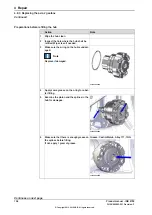
Remove any tool or other equipment fitted
on the turning disc.
2
See
Draining the axis-2 and axis-3 gear-
.
Begin draining the oil.
3
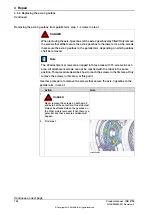
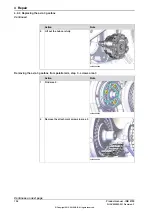
The three areas of screws that secure axis-3 gearbox to parallel arm
The axis-3 gearbox is attached to the parallel arm with attachment screws arranged
in three areas. Use this figure to understand the position of the three areas, when
performing this procedure.
1
2
3
1
2
3
xx1500002974
The order when removing the attachment screws that secure the axis-3 gearbox
to the parallel arm are removed is: area 1, area 2, and then area 3.
The order when attaching the axis-3 gearbox to the parallel arm is reversed: area
3, area 2, and then area 1.
Robot position when removing axis-3 from parallel arm - screws in area 1
With the robot in this position it is possible to reach the screws in the first of the
three areas of screws that secure the axis-3 gearbox to the parallel arm.
Note
Action
Jog the robot to the specified position:
•
Axis 1: no significance as long as
the robot is secured to the founda-
tion.
•
Axis 2: +48°
•
Axis 3: 0°
•
Axis 4: 0°
•
Axis 5: 0°
•
Axis 6: No significance.
1
DANGER
Turn off all:
•
electric power supply
•
hydraulic pressure supply
•
air pressure supply
to the robot, before entering the robot
working area.
2
Continues on next page
Product manual - IRB 8700
721
3HAC052853-001 Revision: F
© Copyright 2015-2018 ABB. All rights reserved.
4 Repair
4.8.4 Replacing the axis-3 gearbox
Continued
Summary of Contents for IRC5 Compact
Page 1: ...ROBOTICS Product manual IRB 8700 ...
Page 16: ...This page is intentionally left blank ...
Page 824: ...This page is intentionally left blank ...
Page 838: ...This page is intentionally left blank ...
Page 840: ...This page is intentionally left blank ...
Page 846: ......
Page 847: ......


