2.3.7 Manually releasing the brakes
Introduction to manually releasing the brakes
This section describes how to release the holding brakes for the motors of each
axis.
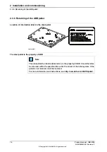
Location of brake release unit
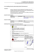
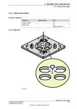
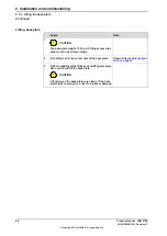
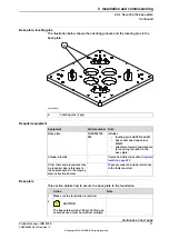
The internal brake release unit is located as shown in the figure.
xx1500001988
Releasing the brakes
This procedure details how to release the holding brakes when the robot is equipped
with an internal brake release unit.
Note
Action
Buttons are shown in figure
tion of brake release unit on
page 77
The internal brake release unit is equipped with
buttons for controlling the axes brakes. The buttons
are numbered according to the numbers of the
axes.
If the robot is not connected to the controller, power
must be supplied to the connector R1.MP according
to the section
Supplying power to connector R1.MP
.
1
Note
The IRB 8700 has two R1.MP connectors: R1.MP-
A and R1.MP-B. How to supply power to the con-
nectors is described in
Continues on next page
Product manual - IRB 8700
77
3HAC052853-001 Revision: F
© Copyright 2015-2018 ABB. All rights reserved.
2 Installation and commissioning
2.3.7 Manually releasing the brakes
Summary of Contents for IRC5 Compact
Page 1: ...ROBOTICS Product manual IRB 8700 ...
Page 16: ...This page is intentionally left blank ...
Page 824: ...This page is intentionally left blank ...
Page 838: ...This page is intentionally left blank ...
Page 840: ...This page is intentionally left blank ...
Page 846: ......
Page 847: ......


