Note/Illustration
Action
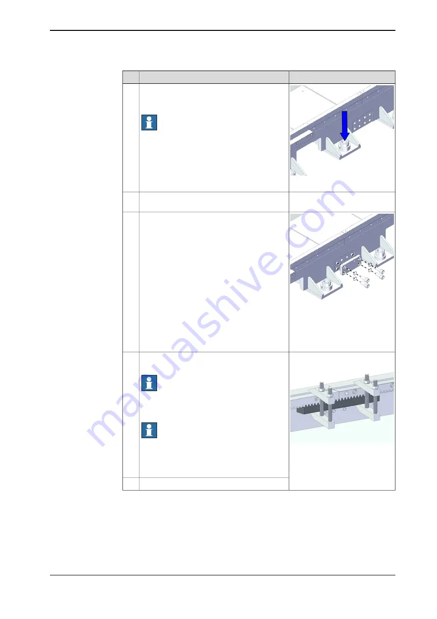
xx2200000669
Level the track module with the M60 screws. See
Geometric alignment of track motion IRT 710 on
page 133
Note
Ensure the geometric alignment of the IRT 710
with an optical level or a laser tracker. Note that,
at this stage, you can only check the horizontal
alignment based on the sidemember upper sur-
face. The final alignment will be given by the
measurements done based on the linear rails po-
sition.
6
Adjust the leveling screws until all leveling screws
touch the ground.
7
xx2200000670
Install the connecting plate and secure without
fully tighten the screws.
8
Screws: ISO 4762 M20x45 Class
8.8
Washers: BN 792 M20 Washer
Tightening torque: 305 Nm ¡À3%
xx2200001170
Install the rack to the section with the rack
mounting block and the rack clamps.
Note
There should be no gap between the rack
mounting surface and the section mounting sur-
face.
Note
Use the clamping and mounting racks at the ends
of the rack section to make sure that the racks
are pushed against the side member mounting
surface and perfectly aligned with each other.
9
Screws: ISO 4762 M8x40 Class12.9
Tightening torque: 43 Nm
Secure with screws.
10
Continues on next page
Product manual - IRT 710
123
3HKA00000186299-001 Revision: B
© Copyright 2023 ABB. All rights reserved.
3 Installation and commissioning
3.4.7.1 Assembling the sections
Continued
Summary of Contents for IRT 710
Page 1: ...ROBOTICS Product manual IRT 710 ...
Page 14: ...This page is intentionally left blank ...
Page 58: ...This page is intentionally left blank ...
Page 84: ...This page is intentionally left blank ...
Page 360: ...This page is intentionally left blank ...
Page 364: ...This page is intentionally left blank ...
Page 378: ...This page is intentionally left blank ...
Page 380: ...This page is intentionally left blank ...
Page 383: ......


