Action
Move the carriage all along the track way, and check the levelling with a levelling
device or a laser tracker. The levelness of the top plate must be satisfying in the
translational direction, but also cross section. If you have moved the carriage manually,
you probably need to initialize the resolver position, see
.
2
Drill the holes in the floor through the levelling screws opening, see the following
section.
3
Install the anchors and secure the cross members to the floor.
4
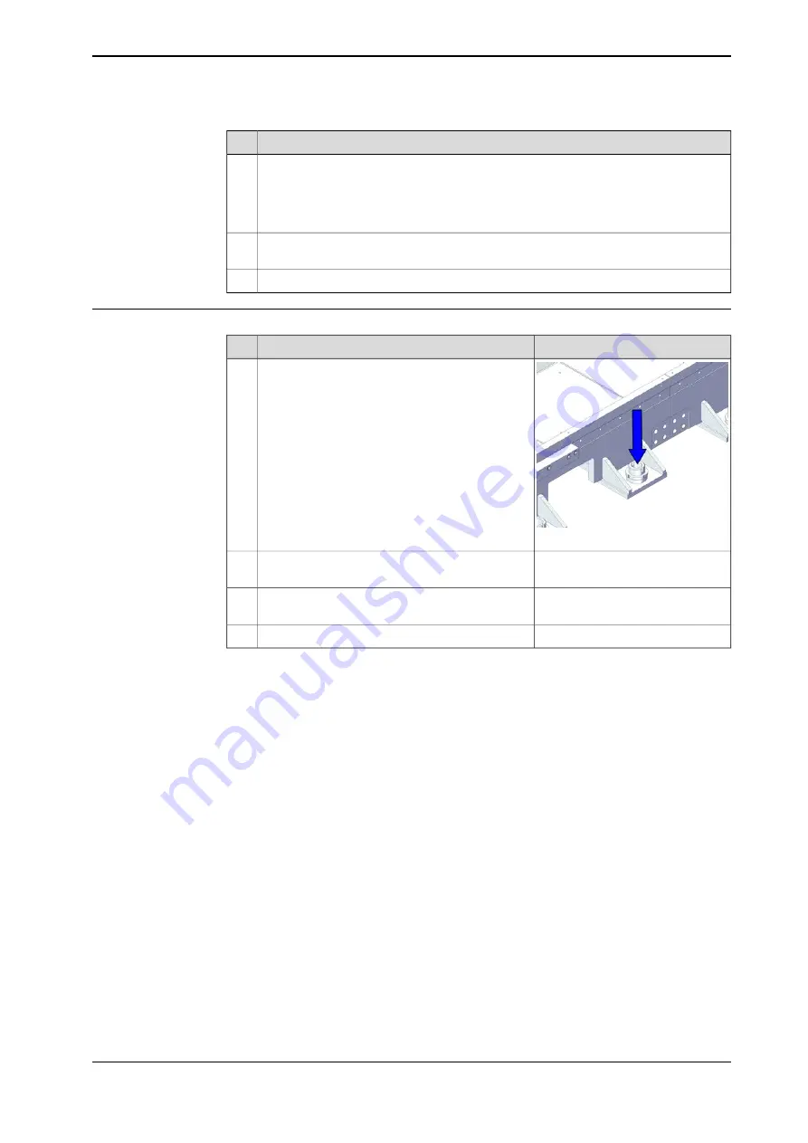
Securing a section
Note/Illustration
Action
xx2200000669
Position the sections on the floor.
1
Adjust the horizontality of the IRT 710 with the
M60 levelling screw.
2
Check that all the levelling screws are touching
the floor.
3
Tighten the M60 nuts.
4
Continues on next page
Product manual - IRT 710
129
3HKA00000186299-001 Revision: B
© Copyright 2023 ABB. All rights reserved.
3 Installation and commissioning
3.4.7.2 Recommendations for floor mounting
Continued
Summary of Contents for IRT 710
Page 1: ...ROBOTICS Product manual IRT 710 ...
Page 14: ...This page is intentionally left blank ...
Page 58: ...This page is intentionally left blank ...
Page 84: ...This page is intentionally left blank ...
Page 360: ...This page is intentionally left blank ...
Page 364: ...This page is intentionally left blank ...
Page 378: ...This page is intentionally left blank ...
Page 380: ...This page is intentionally left blank ...
Page 383: ......


