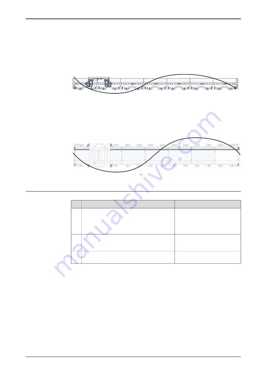
Alignment in Z direction
The figure shows the possible variation along the Z-axis.
The track should be laser aligned to within 0.1 mm from the origin per meter, along
the entire X-axis.
xx2200000787
Alignment in Y direction
The figure shows the possible variation along the Y-axis.
The track should be laser aligned to within 0.1 mm from the origin per meter, along
the entire X-axis.
xx2200000788
Procedure
Note/Illustration
Action
On the foundation where the track will be placed,
use a laser line drawing instrument to draw the
approximate position of the installation position.
Place the track on the drawing position without
installing the anchor bolts.
1
Position the absolute tracker such as you will be
able to measure the reflector position on the linear
rails.
2
Make sure that the absolute tracker is parallel to
the sea level.
3
Continues on next page
134
Product manual - IRT 710
3HKA00000186299-001 Revision: B
© Copyright 2023 ABB. All rights reserved.
3 Installation and commissioning
3.4.7.3 Geometric alignment of track motion IRT 710
Continued
Summary of Contents for IRT 710
Page 1: ...ROBOTICS Product manual IRT 710 ...
Page 14: ...This page is intentionally left blank ...
Page 58: ...This page is intentionally left blank ...
Page 84: ...This page is intentionally left blank ...
Page 360: ...This page is intentionally left blank ...
Page 364: ...This page is intentionally left blank ...
Page 378: ...This page is intentionally left blank ...
Page 380: ...This page is intentionally left blank ...
Page 383: ......


