background image

20

3 6 K V I

S

  LI M ITE R  PA N E L 

I N S TA L L AT I O N ,  O P ER AT I O N  A N D  M A I N T EN A N C E  M A N UA L

4.4 Delivery

The responsibilities of the consignee when the                 
switchgear arrives at site include, but are not limited to, the 
following:
•  Checking the consignment for completeness and 

freedom from damage (e.g. also for moisture and its 
detrimental effects). in cases of doubt, the packaging 
must be opened and then properly resealed, fitting new 
drying agent bags, when intermediate storage is 
necessary

•  If any short quantities, defects or transport damages are 

noted:
-  To be documented on the respective shipping 

document

-  Notify the relevant carrier or forwarding agent 

immediately in accordance with the relevant liability 
regulations

• Note:
 

Always take photographs to document any major 
damage

4.5 Unloading & unpacking

Unloading the switchgear from truck must be carried out by 
appropriate handling methods described in section 4.3.

Unpacking: 

-  Remove wrapping / plastic bag covers, cardboard  

pads etc. 

-  Open the compartment door and loosen the bolts fixing 

the switchgear to pallet

-  Lift the switchgear by crane following instructions  

given below:


remove the pallet


position unloading shims


put the switchgear on loading shims using crane

The packing is intended for transport and not for storing 
purpose. Upon receipt, the switchgear must be unpacked 
and installed under clean, dry, dust-free, indoor conditions 
and anti-condensation heaters shall be switched ON.

4.6 Intermediate storage

Optimum intermediate storage where it is necessary – 
without detrimental consequences depends on compliance 
with a number of minimum conditions for the panels and 
assembly materials

1.  Panels with seaworthy or similar packaging with internal 

protective sheeting:
•  Store the transport units:

-  protected from the weather
-  in a dry place
-  safe from damage

•  Check the packaging for damage
•  Check the drying agent (see also section 4.2):

-  on arrival of the consignment
-  later at regular intervals

•  When the maximum storage period, starting from the 

date of packaging, has been exceeded:
-  the protective function of the packaging can no 

longer be guaranteed

-  take suitable action if intermediate storage is to 

continue

Note

Do not walk on the roof of the panel 
(rupture points in pressure relief device)!

Note

For the panels which are stored for intermediate periods 
after unpacking, where panel is subjected to direct 
ambient / environmental conditions it is recommended to 
arrange auxiliary supply near panel & to keep heaters 
inside the panel ON to avoid condensation / dew deposits 
inside the panel.

Summary of Contents for IS-limiter

Page 1: ... 36kV I s limiter TM panel Installation operation and maintenance manual DISTRIBUTION SOLUTIONS 36kV IS limiterTM panel Installation operation and maintenance manual ...

Page 2: ... phase metal enclosed air insulated switchgear and all units are factory assembled type tested and suitable for indoor applications up to 36 kV The panels are fitted with Is limiterTM switch inserts as fixed installation along with CTs busbars ...

Page 3: ... practices Ensure that operating conditions are within the specified operating limits Pay special attention to the hazard notes in the instruction manual marked with this warning symbol Danger Do not exceed the loads quoted in the technical data of the specification in normal operation of the switchgear or switchboard Keep the instruction manual accessible to all persons concerned with installatio...

Page 4: ...ection of the switchgear on site 5 1 General site requirements 5 2 Foundation 5 2 1 Checking of foundation 5 2 2 Mounting of cubicle on foundation frame 5 3 Erection of the panels 5 4 Fixing IS limiterTM inside the panel 5 5 Connection of the power and control cable 5 6 Earthing the switchgear 5 7 Concluding installation work 24 27 6 Commissioning operation 6 1 Commissioning 6 1 1 Preparatory work...

Page 5: ... operating conditions for indoor switchgear and switchboards in accordance with IEC Publication IEC62271 200 The following limit values among others apply Ambient temperature Maximum 40 C Maximum 24 hour average 35 C Minimum according to minus 5 indoor class 5 C With indoor installation it is assumed that the humidity within the enclosure can reach high values but that there is normally no condens...

Page 6: ... 1250 2000 25001 Peak withstand current kAp 100 Rated short time current 3s kA 40 Rated control supply voltage V DC 110 220 AC 110 220 1 With cooling fan Dimensions and weight Dimensions Height mm 28451 Width mm 13002 Depth mm 2345 Weight including Is limiterTM switch kg 2200 1 Including absorber assembly Without absorber assembly 2610 2 Including end covers 1300 2610 2345 2345 1300 2845 Overall d...

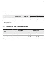
Page 7: ...sert holder Is limiterTM insert kV A kV kVp Kg Kg 36 1250 2000 25001 70 170 60 42 1 With cooling fan installed in panel 2 3 Tripping device and auxiliary circuits Electrical data Device Power consumption1 Rated supply voltages AC VA DC W AC f 50 60 Hz V DC V Tripping device 80 110 220 Auxiliary circuits blocking magnet auxiliary relay 60 110 220 110 220 1 approximate values ...

Page 8: ...sists of Aluzinc steel sheets which are rivetted to each other The roof of the high voltage compartment is fitted with integrated pressure relief devices These devices open when overpressure occurs as a result of an internal arc fault The front is sealed off by flame proof doors with hinges at the left and an opening angle of approx 1800 At rear side there are rear covers provided to have access t...

Page 9: ...ight side duct Warning In order not to alter the electromagnetic compatibility EMC of the tripping device no additional wiring may be installed parallel to the following connections or laid in the conduits later date connection between the movable hinged frame where the tripping device is located and the anti interference unit connections between tripping current transformers and clamps connection...

Page 10: ...ted Insulators for 36 kV are fitted with a pulse transformer This transmits the tripping pulse from the tripping device to the charge 3 in the Is limiterTM insert tube and at the same time serves to isolate the tripping device electrically from the charge at system potential The telescope contacts 7 are located on the insulators fitted with pulse transformers The clamping device is activated by a ...

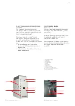
Page 11: ...nal transformers The particularly notable characteristics of the special transformer are an extremely high overcurrent factor an iron core with air gap to keep remnant induction low a low resistance shield between the primary and secondary sides 3 5 4 Tripping device Figure 3 1 The tripping device is installed in the separate low voltage compartment above the Is limiterTM compartment For details o...

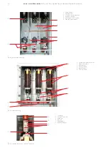
Page 12: ...der 6 Jaw type fixed contact Fig 3 2 Insert holder mounting 4 3 2 4 1 5 6 Fig 3 3 Insert mounting 1 Contacts for cable connection 2 Support insulators 3 Steel channel 4 Locking handle 5 Fuse assembly 6 Is limiter insert 6 5 4 1 2 3 1 T contact 2 Is limiterTM top side 3 Hardware 4 Jumpers 5 Earthing bolt 6 Insulator support Fig 3 4 Top side connection Is limiterTM assembly 1 6 5 4 3 2 ...

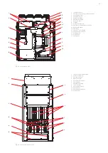
Page 13: ...G cable connection 11 Rear phase barrier 12 Rear cover 13 Is limiterTM insert holder 14 Phase barrier supports 15 Earthing bolt 16 Earthing bar 17 Cooling fan 1 Is limiterTM insert R Y B phase 2 Lever for clamping 3 Insulator support 4 Right side cover 5 LV compartment door 6 Dummy door 7 Absorber assembly 8 Left side cover 9 Structure assembly 10 Phase barrier 11 Phase barrier support 12 Earthing...

Page 14: ...iter assembly 1 Bursting bridge 2 Is limiterTM insert assembly 3 Charge 4 1 Top pole head 4 2 Bottom pole head 5 1 Top insulator 5 2 Bottom insulator 6 Main conductor 7 Tripping contact 8 Mounting hardware 9 Mounting bracket 10 Insulating tube 11 Fuse 9 5 1 4 1 7 2 1 6 3 11 10 7 4 2 5 2 8 ...

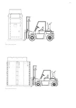
Page 15: ...15 Fig 4 1 Handling with forklit Fig 4 2 Handling with forklit ...

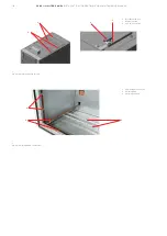
Page 16: ... 36KV IS LIMITER PANEL INSTALL ATION OPER ATION AND MAINTENANCE MANUAL Fig 4 3 Mounting of lifting hooks Lifting hooks mounted on side sheet Side sheet Lifting hook Fig 4 4 Lifting with crane Lifting hook ...

Page 17: ...on 1 Cable lug 2 Hardware 3 Insulator support 4 Cable gland 5 Is limiterTM assembly 6 Cable connection piece 7 Single core power cable 1 Cable lug 2 Hardware 3 Insulator support 4 Cable gland 5 Cable connection piece 6 Single core power cable 3 2 1 4 6 5 7 4 3 5 2 1 6 4 ...

Page 18: ...N OPER ATION AND MAINTENANCE MANUAL 3 2 1 3 1 3 2 1 Bracket for switch 2 Explosion vent 3 Aux switch for flap 1 Cable support channels 2 Earthing bars 3 Earthing support Fig 5 3 Auxiliary switches for flap Fig 5 4 Earthing bars connections ...

Page 19: ...ive humidity above 40 4 3 Transport Figure 4 1 4 4 Normally each individual panel is a separate transport unit The panels are fixed on wooden pallet with bolts The foundation frame for installation at site is packed separately during dispatch of panel for transport to customer site Following precautions must be taken during transport of the panels Transport switchgears upright Take the high center...

Page 20: ...switchgear on loading shims using crane The packing is intended for transport and not for storing purpose Upon receipt the switchgear must be unpacked and installed under clean dry dust free indoor conditions and anti condensation heaters shall be switched ON 4 6 Intermediate storage Optimum intermediate storage where it is necessary without detrimental consequences depends on compliance with a nu...

Page 21: ...mm galvanized steel strip Two connections are necessary for relatively long switchgear 5 2 2 Mounting of cubicle on foundation frame As the switchgear delivered from factory is pallet mounted it should be unloaded from pallet as close as possible to its foundation frame s location to ensure minimal movement of switchgear on the ground Please ensure that the switchgear is vertical when mounted on i...

Page 22: ...ing the knob handle clockwise as shown in figure 3 3 Repeat above 6 steps twice to fix Is limiterTM insert of Y B phases respectively CAUTION Only ever use the correct inserts as specified for the particular Is limiterTM insatallation Observe the label on the Is limiterTM switch As a general rule all the Is limiterTM inserts must be fitted When fitting ensure that the tripping contacts s 7 Fig 3 7...

Page 23: ...ram and specific instructions refer wiring diagrams in the order documentation and notes in section 3 3 to preclude mutual interference 5 6 Earthing the switchgear Figure 5 4 Connect the main earthing bar 2 of the switchgear panel by using the prepared links Make the protection conductor connection to the foundation frame Connect the earthing conductor coming from the ground electrode preferably v...

Page 24: ...age testing of the main circuits to IEC 62271 1 as far as necessary Pay special attention during this procedure to voltage transformers pulse transformers and cables etc CAUTION In order to avoid tripping of the Is limiterTM during the high voltage and impulse voltage tests an insulating disk or cap must be inserted between telescope contact and tripping contact 7 Figure 3 7 Ensure CT secondary is...

Page 25: ...connectors in series are enabled 6 3 Switching operation The tripping device is switched ON and off with the main switch on the power unit The MCB normally remain permanently ON Note If the tripping device is switched ON without resetting the tripped indication it has to be switched off again at the main switch Reset the tripped indication after approx 1 minute and then turn the main switch ON aga...

Page 26: ...ecure against reconnection Carefully observe all safety regulations Check the area to be earthed for the off circuit condition e g with a voltage tester in the measuring point sockets of the capacitive voltage indicator system if fitted or with a high voltage tester at the relevant earthing points First firmly bolt the common earthing cable to the earthing point and then use the insulated rod to c...

Page 27: ...he measuring cables to precisely the corresponding main conductor sections Follow the directions for the phase comparator in detail 6 6 3 Tests on the pulse transformer No continuity tests may be performed on the higher voltage side winding secondary winding of the pulse transformer as otherwise this might destroy the electronic components cast into the pulse transformer The following operating in...

Page 28: ...t procedures must also be referred where ever applicable If necessary further details can be taken from the technical documentation for the switchgear including for example any agreed special operating conditions 7 2 Inspection Before inspection where required the working area must be isolated and secured against reconnection in accordance with the Safety Regulations specified by IEC and appropria...

Page 29: ...5M Wipe down after cleaning using clean water and dry properly Should external discharges occur as a result of condensation application of a thin silicone film on the surface concerned is often effective as a temporary remedy It is advisable to request advice from the ABB after sales service department on permanent solutions to such unusual problems Check that the bolt connections at the contact p...

Page 30: ...special color Carefully remove any white rust from aluminum zinc surfaces with a wire brush or Scotch Brite and remove loosely adhering particles with a dry non fraying cloth Then treat the cleaned areas with zinc spray or zinc dust paint and then with aluminum spray to match up the color Carefully remove any white rust on chromium plated functional parts and rust on phosphatized parts with a wire...

Page 31: ...tch disconnector must receive opening commands Check this condition as follows Effect a trip using test plug QT3a or test equipment QT2b with the IS limiterTM inserts removed 3 Any additional interlocks fitted and listed in the order documentation are to be tested separately 7 6 Spare parts auxiliary materials 7 6 1 Spare parts The list of spare parts is available on request The following details ...

Page 32: ...ring disposal of product it is always necessary to act in according with local legal requirements in force The following methods of disposal are possible Disposal can either be carried out thermally in an incineration plant or by storing on a waste site Raw material material Recommended method of disposal Metal material Fe Cu Al Ag Zn W others Separation and recycling Thermoplastics Recycling or d...

Page 33: ...33 ...

Page 34: ...ithout prior notice With regard to purchase orders the agreed particulars shall prevail ABB does not accept any responsibility whatsoever for potential errors or possible lack of information in this document We reserve all rights in this document and in the subject matter and illustrations contained therein Any reproduction disclosure to third parties or utilization of its contents in whole or in ...

Reviews: