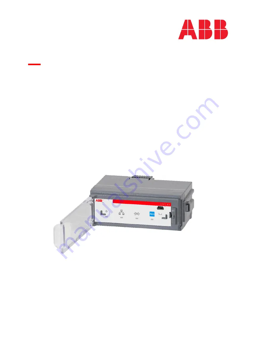
background image

 USER MANUAL

ITS2.1

Slimline, InlineII and Standalone ITS2

Summary of Contents for ITS2.1

Page 1: ...USER MANUAL ITS2 1 Slimline InlineII and Standalone ITS2 ...

Page 2: ...minal 23 6 1 Slimline XRG and Inline II ZHBM ITS multiplug 23 6 2 Standalone ITS module multiplug 24 7 modbus RTU 25 7 1 Special sequence Modbus telegram 25 7 2 Modbus RTU trouble and fault finding 25 7 3 Modbus RTU cabling 26 7 3 1 Terminating resistors TR 26 7 3 2 Grounding of shielding 26 8 Ekip com modbus tcp module 27 9 Cyber security 28 10 Power direction setting 29 10 1 Slimline XRG power d...

Page 3: ...0001 3 1 PRODUCT OVERVIEW 1 1 Slimline XRG00 Refer the installation instruction for XRG00 ITS2 1 2 Slimline XRG1 Refer the installation instruction for XRG1 ITS2 1 3 Slimline XRG2 and XRG3 Refer the installation instruction for XRG23 ITS2 ...

Page 4: ...ITS2 1 User Manual rev 04 1SEP622750P0001 4 1 4 Inline II ZHBM00 Refer the installation instruction for InlineII ZHBM ITS 1 5 Inline II ZHBM123 Refer the installation instruction for InlineII ZHBM ITS ...

Page 5: ...Switch opened by motor operation when fuse blown 2 Hz Power LED The power LED can be configured in two ways Power indication with a steady light Alive indication with a flash rate of Hz When configuring the light is in WINK LED mode 2Hz Local Remote indicator LED and pushbutton Local Remote LED indicates as follows 2 Dark Local mode commands or setting of parameters are refused Lit Remote mode com...

Page 6: ...Order code 1SDA076154R1 Ekip T P unit is suitable for ITS2 1 You can connect the module via the programming port as below The programming port can only be used with Ekip T P Ekip T P unit allows you to update the software as well as load set and read the parameters on Ekip Connect software Connect one side of cable B to the programming unit A and the other side of cable B to ITS2 1 programing port...

Page 7: ...nect and check for latest update Start Ekip Connect For a more extensive guide please refer to Ekip Connect user manual Searching for latest version of Ekip Connect and Device Description files are quite easy However the computer must have access to internet to check for and download an update ...

Page 8: ...he ITS2 1 unit 1 Select Switch type according to the actual switch type five basic switches Slimline XR InlineII OS OT or Other can be selected each switch type has several different current sizes make sure your switch type and rated current are all correct 2 Set Nominal Line Voltage according to the system voltage If the line voltage in the system is 400 V the Nominal Line Voltage should be set e...

Page 9: ...t for XRG 1 2 and 3 The straps on the fuse boards inside the XRG apparatus must be set according to the feeding direction When changing the power direction these must be changed accordingly study chapter 8 Inline II Busbar Side Terminal Side Busbar side Terminal side ...

Page 10: ...e ITS unit a unique Modbus slaver address between 1 247 If necessary the communication parameters must be changed to correspond with system builder s settings factory setting is 247 5 If an Ekip Com Modbus TCP module is connected the module s static IP address can be force set at Ekip COM Modbus TCP page Information After you modified the parameters on each page click Apply button to download the ...

Page 11: ...rrent and time limit ca be set When the current limit is exceeded the timer will start Once both the current limit and the time limit are exceeded an alarm will be signaled or the motorized switch will switch off If the current level goes back to accepted level timer will stop and no signal will be sent Fuse protection switch open Enable This function is relevant only if the switch is equipped wit...

Page 12: ... and running POWER MODE There is a steady light in the power LED A hangup due to software failure will not be indicated CUSTOM FIELDS Tag name The customer can enter a relevant name User data The customer can enter a relevant data Switch Installation Date The customer can enter the switch installation date MINIMUM CURRENT VALUE Minimum current value Sets the threshold for the minimum value for the...

Page 13: ...d current Ie 160A 250A 400A 630A 800A 1000A 1250A 1600A 2000A 2500A Nominal line voltage Ue Shows configured nominal voltage NOT measured ITS2 1 Serial number Located on label outside of unit Electronic board serial no Located on label on board Firmware version Firmware subversion CURRENTS L1 L2 L3 Measured currents ...

Page 14: ... switch If equipped with motor switch will open when selected Close switch If equipped with motor switch will close when selected Wink Power LED flashes with 2 Hz when selected ITS STATUS Supply from Vaux Should indicate YES when the ITS2 unit is fitted into a main switch and 24 VDC is present Supply from test YES when the ITS2 unit is connected to a laptop by T P Local Remote operating mode Remot...

Page 15: ...nd configured to open when one or more fuses are blown Temperature sensor status Shows status of temperature sensor Nominal voltage status The Electronic Fuse Monitor EFM uses the measured line voltage when determining if one or more fuses are blown or not hence the correct nominal line voltage must be configured by the user By factory default the nominal line voltage is set to an invalid value fo...

Page 16: ...16 5 3 All Measures CURRENTS L1 L2 L3 Actual currents FREQUENCY Frequency Actual frequency VOLTAGES V1N V2N V3N Actual phase voltages 1 V12 V23 V31 Actual line voltages 1 1 Accuracy of measured voltages depend on a symmetric equilibrated system ...

Page 17: ...hase power factor TEMPERATURE Temperature Actual temperature measured ENERGIES Active energy positive Calculated positive active energy kWh Active energy negative Calculated negative active energy kWh Active energy total Sum of positive and negative active energy kWh Reactive energy positive Calculated positive reactive energy kvarh Reactive energy negative Calculated negative reactive energy kvar...

Page 18: ...l currents V1N V2N V3N Actual phase voltages 1 V12 V23 V31 Actual line voltages 1 1 Accuracy of measured voltages depend on a symmetric equilibrated system Ptot Calculated 3 phase active power kW Qtot Calculated 3 phase reactive power kVAR Cos phi tot Calculated 3 phase power factor Active energy total Sum of positive and negative active energy kWh Temperature Actual temperature measured on L2 cab...

Page 19: ...ual min max frequency Temperature min max Actual min max temperature POWERS P1 P2 P3 min max Calculated min max active power kW Ptot min max Calculated min max 3 phase active power kW Q1 Q2 Q3 min max Calculated min max reactive power kVAR Qtot min max Calculated min max 3 phase reactive power kVAR S1 S2 S3 min max Calculated min max complex power kVA Stot min max Calculated min max 3 phase comple...

Page 20: ... bit N 8 2 No parity bit 8 data bits 2 STOP bits N 8 1 No parity bit 8 data bits 1 STOP bit Modbus communication statistics Embedded System bus N of messages received Number of messages received by Ekip connect from ITS N of messages received with CRC error Number of messages received by Ekip connect with CRC error from ITS N of messages sent Number of messages sent by Ekip connect to ITS N of mes...

Page 21: ...dules adopt an Autoconfiguration IP Address in the range 169 254 xxx xxx calculated in a pseudo random manner so as to be the same at every switch on Alternatively you can enable the static IP address option which allows the IP address to be forced in this case you must make sure that the IP Address inserted is different to that of the other devices connected to the same network Network Mask This ...

Page 22: ...ddress Displayed with the static IP Address enabled it must be selected in order to insert the IP address of the modules Static Network Mask Displayed with static IP Address enabled it must be selected in order to insert the subnet mask of the modules Static Gateway address Displayed with static IP Adress enabled it must be selected in the persence of multiple subnets in order to insert the IP Add...

Page 23: ...minal with screw is used and assembled on the ITS adapter Slimline XRG Multi plug terminal Terminal pins definition Terminal Signal Cable X1 1 24 VDC power supply input AWG22 16 300 500V Temp 125 X1 2 24 V GND 0V X1 3 RS 485 0V Belden 3105A or equivalent X1 4 RS 485 A X1 5 RS 485 B InlineII ZHBM Multi plug terminal Terminal pins definition Terminal Signal Cable X1 1 24 VDC power supply input AWG22...

Page 24: ... X2 5 L1 Current sensing signal Negative AWG18 300 500V Temp 125 X2 6 Switch position input signal Positive AWG24 300 500V Temp 125 X2 7 Not in use X2 8 Switch control common port AWG24 300 500V Temp 125 X2 9 Temperature sensor emitter polar ABB provides X2 10 ITS GND 0V ABB provides X2 11 L3 Current sensing signal Positive AWG18 300 500V Temp 125 X2 12 L2 Current sensing signal Positive AWG18 300...

Page 25: ...ming the Modbus line is OK hardware vice correct polarity no similar addresses trouble with termination reading of Modbus register issues etc a laptop with USB RS 485 converter and Ekip connect can be used for testing the Modbus line It will even handle multidrop Modbus address Parameters Comment 100 104 L1 L2 L3 Actual current measure by the CT s 150 152 V1N V2N V3N Actual phase voltages 154 156 ...

Page 26: ...addition to the ITS it is necessary to verify whether they are equipped or not with terminating resistors in this case it is usually possible to activate or deactivate it Termination resistors must be used only at both ends of the main cable If the total length of the main cable is less than 50 m the termination resistors at both ends of the main cable can be avoided 7 3 2 Grounding of shielding T...

Page 27: ...necessary safety measures are adopted for example firewalls and so on The module cannot be connected directly to the Internet it is recommended to connect it only to dedicated Ethernet networks with the Modbus TCP communication protocol For the communication bus a cable of type Cat 6S FTP must be used Cat 6 with S FTP double shielding The following table illustrates the possible signals of Ekip co...

Page 28: ...or losses related to such security breaches unauthorized access interference intrusion leakage and or theft of data or information Secure Deployment The user of the product should be aware that the unsecure nature of the serial Modbus protocol exposes the communication between the product and the control system Encryption authentication or integrity of transmitted data are not provided by the prot...

Page 29: ...d behind the fuses in correct position By default the straps are set in the position marked Busbar Feed Note Make sure the feeding side setting in Ekip connect aligns to the power direction setting on slimline XRG1 2 and 3 can be fed from the busbar side busbar feed or from the cable terminal side terminal feed By default the straps are set in the position marked Busbar Feed and the corresponding ...

Page 30: ...ITS2 1 User Manual rev 04 1SEP622750P0001 30 ...

Page 31: ... is set when connect to KM5 Terminal Feed is set By default the jumper is connected to KM6 so the default mode is Busbar Feed Note Make sure the feeding side setting in Ekip connect aligns to the power direction setting on Inline ZHBM can be fed from the busbar side busbar feed or from the cable terminal side terminal feed By default the jumper is connected to KM6 and the corresponding feeding sid...

Page 32: ...his application ITS and adapter module needs to be fixed separately and connected to switch by external cable refer to the ITS standalone product installation instruction The power direction setting is done by users themselves just connect the three phase voltage cables from outgoing side to the voltage sensing connector X3 on the standalone ITS Note In Ekip Connect keep the feeding side is BUSBAR...

Page 33: ...t 1 Electronic Fuse Monitoring detection level Nominal line to line voltage 20 Electronic Fuse Monitoring operating time 1 s Modbus communication and configuration Default setting 19200 E 8 1 Default Modbus addr 247 Baudrates 9600 19200 Parity stop start bits E 8 1 O 8 1 N 8 2 N 8 1 Modbus address range 1 247 Configuration tool Ekip connect Termination resistor No internal resistor If needed place...

Page 34: ...s product Slimline XRG23 ITS2 Installation instruction 1SEP619493P0001 Follows product Inline II ZHBM ITS Installation instruction 1SEP622739P0001 Follows product ITS2 1 Standalone Module Installation instruction 1SEP622726P0001 Follows product Modbus mapping 1SEB000478 System interface ITS2 1 Technical Application Papers No 9 Bus communication with ABB circuit breakers 1SDC007108G0202 Cover ABB S...

Page 35: ...ITS2 D WITH EKIP DISPLAY Information ITS2 D with Ekip display is only available for Slimline XRG switch 13 1 How to plug in the Ekip Display at an XR ITS2 1 unit 1 Press in the 3 dedicated areas at the ITS2 1 front panel for fixing the Ekip Display unit ...

Page 36: ...ide pin at the left side and then the USB connector 2 at the right side 3 Fix the Ekip Display by rotating the closing button to closed position by using a screw driver The ITS2 D can be connected to a laptop for configuration by using the T P cable unit to the USB connector at the lower side of the Ekip Display unit 1 2 ...

Page 37: ...ew Ekip Display LCD view area is divided in 2 separate section Signalling area and Menu area Menu area can have different behaviour views depending on where you are in the navigation tree Signalling area behaviour is fixed see Ekip display signalling area paragraph Scroll to the right Scroll to the left Power One level up Confirm one level down Enter key Closing device for fixing the Ekip Display ...

Page 38: ...ion on the bus Communication on the bus but no address to ITS undefined b 4 status alternatives for XR MOT 3 status alternatives for XR manually operated Icon Description Fuses OK Fuse blown FB Voltage undefined Fusegear open after automatic switch off by the MOT Available at XR MOT only parameter setting at Ekip Connect or at the Display settings C 2 status alternatives at XR MOT only Icon Descri...

Page 39: ...me is shown cycling through all the active icons in loop Table 1 Signalling area icons Icon Description Local Remote setting of XR ITS2 D when MOT Motor ON if power supply is present ON if communication between ITS Ekip Display is lost ON if Plant nominal voltage is INVALID ON if Fuse blown ON if Fuse is blown and the MOT has disconnected the apparatus ON if no communication with the SCADA system ...

Page 40: ...sing the button Top Level Menu In Table 2 is illustrated the navigation tree of the actual Ekip Display unit Top Level Menu Second Third and Forth Level Horizontally navigation next previous level is achieved by the ENTER and ESC keys vertically navigation move right left through menu or page of the same level is achieved by the ARROWS keys ...

Page 41: ...the MOT to disconnect the apparatus when a fuse is blown Power direction To select if the supply is from the Busbar side or the Terminal side Only for XR size 1 2 and 3 Nominal Voltage Nominal Voltage has to be set Minimum current value Minimum level measured current 0 5 2 of rated max current of the XR apparatus size LED mode Power indicator Selectable pulse or fixed LED Local Remote Local Remote...

Page 42: ... Menu Communication Modbus slave address 1 247 Parity Data stop bits Baud rate Information XR size XR00 XR1 XR2 XR3 In 160A 250A 400A 630A Vn 100V 690V ITS SW Version ITS Serial No Electronic Board Serial No Display SW Version Settings After you remove the display it takes about 2s time out to light on the LED and take re activate LOC REM push button ...

Page 43: ...type may be set as InlineII but InlineII has no motor Check switch type setting on Ekip connect Main page and correct it on ITS2 configuration page Fuse blown function cannot work This function wasn t enabled Check Fuse blown handling setting on Ekip connect Main page and correct it on ITS2 configuration page Nominal line voltage wasn t set correctly Check nominal line voltage setting on Ekip conn...

Page 44: ...ITS2 1 User Manual rev 04 1SEP622750P0001 44 Contact Us ABB Oy P O Box 622 FI 65101 Vaasa Finland www abb com fusegear ...

Reviews: