Page 11
© 2021 ABB. All rights reserved.
Version 1.0
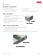
Step 3 –
Connect AC input
The AC input is provided through a IEC
-
C19 connector or 3 pin
terminal connector based on the configuration of the shelf
discussed as below:
For J2007003L301AB and J2007003L301A Configurations:
•
Connect the IEC
-
C19 AC input cable to the C19 connector
provided at the rear side of shelf.
For J2007003L301CB and J2007003L301C Configurations:
•
Use the thumb screw to remove the AC cover provided at
the rear side of shelf.
•
Route the cable through the hole in the AC cover.
•
Wire size recommended is 12 AWG with ferrule.
•
Strip wire
3/16”
•
Insert wire fully into wire entry of the female 3 pin terminal
connector.
•
Tighten the screw
(1/16”
flat screw driver).
•
Connect the 3
-
pin female connector to the AC input terminal
of the shelf.
•
Mount the AC cover back over the input and tighten the
thumb screw.
Danger: Turn OFF and lock
-
out tag
-
out the AC source before
making AC connections. Follow all local and national wiring rules.
Caution: Route AC cables to avoid contact with sharp or rough
surfaces that may damage insulation and cause a short circuit.
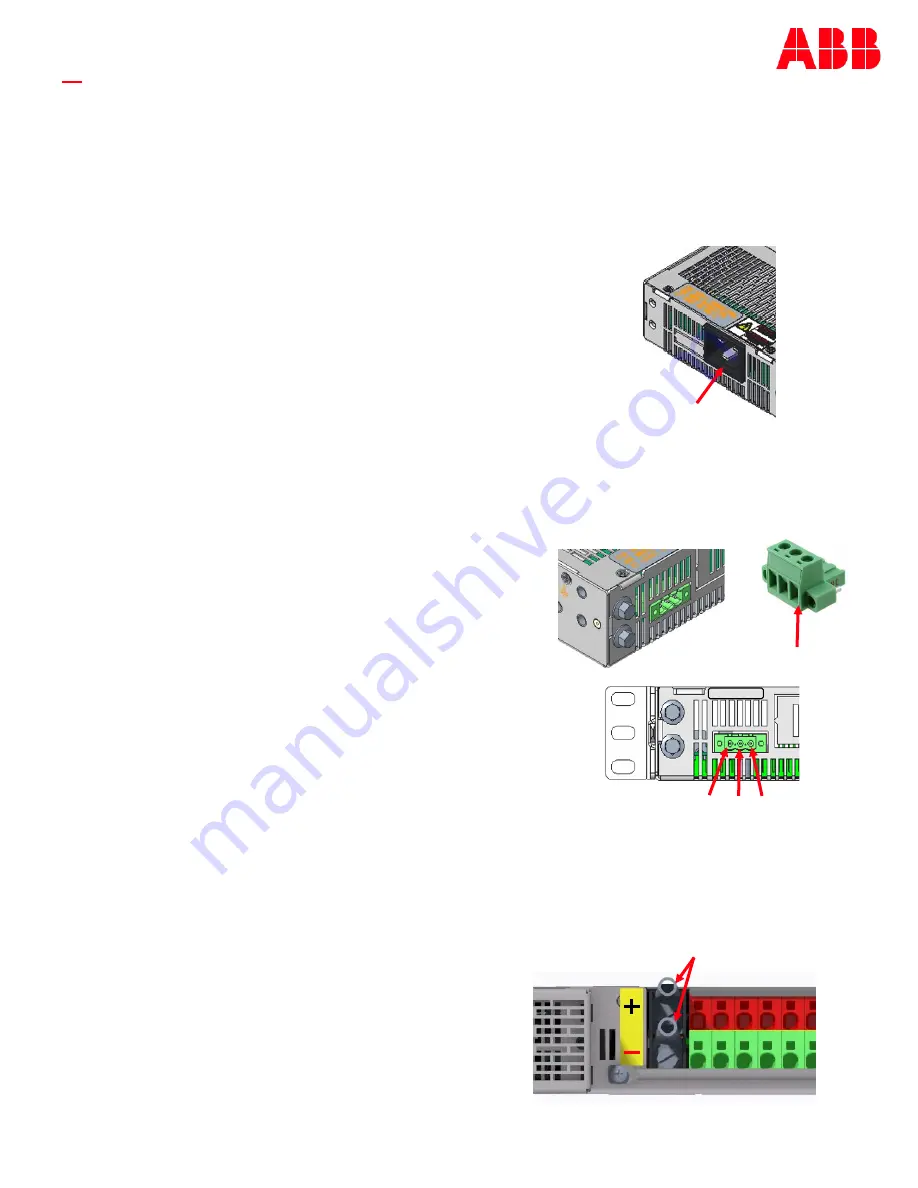
Figure 6: AC Input IEC–
C19 Connector
AC Input (C19 Connector)
Figure 7: AC Input Terminal block Connector
AC Input (3
-
pin
terminal connector)
L1
PE
L2/N
Phoenix Mating
connector
L1 L2/N PE
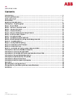
QUICK START GUIDE
Step 4 –
Connect Battery (Only applicable for J2007003L301CB and
J2007003L301CB)
Wire size: 6AWG
Lug landing: Single hole 90° lugs, 6AWG size
Screw size: 10
-
32
1.
Attach single lugs to the wire .
2.
Connect the lugs to the bus bar.
3.
Torque the screw to 30 in
-
lb (3.4Nm).
Figure 8: Connect Battery
Lugs
(GND)
48VDC


