background image

— 

A B B ME A SUR EMENT & A N A LY TIC S | OPER ATING INSTRUC TION

JDF300

Field indicator with 
FOUNDATION Fieldbus communication

The field indicator JDF300 provides 
simple and low cost remote 
indication of a process variable on 
an easy to read LCD display.

Measurement made easy

Introduction

The present manual provides information on 
installing, operating, troubleshooting the field 
indicator JDF300. Every section of the present 
manual is specifically dedicated to the specific 
phase of the field indicator lifecycle starting from 
its receipt and identification, passing to the 
installation, to the electrical connections, to the 
configuration and to the troubleshooting and
maintenance operations.

The present manual can be used for JDF300 field 
indicator.

The new JDF300 Foundation Fieldbus indicator 
provides remote visibility for up to 8 variables, 
subscribed from the bus (publisher/subscriber) or 
directly written by the Host (client/server).
Each individual variable/input to be displayed can 
be remotely selected through FF protocol or locally 
selected operating on the housing push button or 
through the local display menu: such delocalized 
configuration capabilities saves time and greatly 
improve productivity.
In addition to its standard function of Field 

Indicator, the JDF300 is a Link Master device and 
offers a set of Control Function Blocks improving its 
calculation capability available for distributed 
control strategy solutions. 

For more information

Further publications for JDF300 are available
for free download from:

www.abb.com/measurement

 
or by scanning this code:

Search for or click on:

JDF300 field indicator –

Datasheet

DS/JDF300-EN


JDF300 field indicator –


Operating Instruction

OI/JDF300-EN


JDF300 field indicator

Summary of Contents for JDF300

Page 1: ...oundation Fieldbus indicator provides remote visibility for up to 8 variables subscribed from the bus publisher subscriber or directly written by the Host client server Each individual variable input to be displayed can be remotely selected through FF protocol or locally selected operating on the housing push button or through the local display menu such delocalized configuration capabilities save...

Page 2: ... General risk for JDF300 used in zone 0 8 Installing JDF300 field indicator 8 Bracket mounting 8 Securing the housing cover in flameproof areas 9 6 Field indicator wiring 9 Cable connection 9 Supply requirement 10 Grounding 10 Wiring procedure 10 7 Electronic board 11 Fault Protection 11 On board switches 11 8 Display 12 Configuration of the field indicator using the optional integral LCD with key...

Page 3: ...ic 41 OUT status 41 Troubleshooting 41 Control Selector Function Block CS 42 Overview 42 Block diagram 42 Description 42 Equations 42 Configuration hints 42 Block mapping 43 Diagnostic 44 OUT status 44 Troubleshooting 44 11 Maintenance 45 Returns and removal 45 Basic maintenance activities 45 12 Hazardous Area considerations 46 Ex Safety aspects and IP Protection Europe 46 Important Note for field...

Page 4: ...y engineering standards regarding maintenance and use of adequate safety systems For safety reasons ABB draws your attention to the fact that only sufficiently insulated tools conforming to DIN EN 60900 may be used Since the field indicator may form part of a safety chain we recommend replacing the device immediately if any defects are detected In case of use in Hazardous Area non sparking tools o...

Page 5: ...nly For information on permissible ambient conditions for storage and transport see Technical data Although there is no limit on the duration of storage the warranty conditions stipulated on the order acknowledgment from the supplier still apply Safety information for electrical installation Electrical connections may only be established by authorized specialist personnel in accordance with the el...

Page 6: ...ion concerning product code output signal tag and product serial number see Ref A Please refer to this number when making enquiries The Safety Marking plate provides information of Ex protection it is filled with necessary Ex information only when the indicator is for Hazardous Area installation see Ref B Local keys below label FM18CA0110X FM18US0231X Figure 2 Product identification HMI display wi...

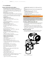
Page 7: ...ions carefully before proceeding Failure to observe the warnings and instructions may cause a malfunction or personal hazard Before installing the field indicator check whether the device design meets the requirements of the measuring point from a measurement technology and safety point of view This applies in respect of Environment corrosion Explosion protection certification Temperature Operatin...

Page 8: ... db IIC T4 Gb Flameproof Canada Class I Zone 1 Ex db IIC T4 Gb Intrinsically safe Class I Zone 0 AEx ia IIC T6 T4 Ga US Class I Zone 0 Ex ia IIC T6 T4 Ga Canada Class I Division 1 Groups A B C D T6 T4 Class II Division 1 Groups E F G T6 T4 Class III when connected per drawing 3KXP000074U0109 FISCO Field Instrument Energy limited US Class I Zone 2 AEx nC IIC T6 T4 Gc Energy limited Canada Class I Z...

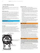
Page 9: ...sent on leads can cause electrical shock Do NOT make electrical connections unless the electrical code designation agrees with the classification of the area in which the field indicator is to be installed Failure to comply with this warning can result in fire or explosion To remove the LCD unscrew the housing cover by turning it Unplug the LCD by pulling it out gently On the field indicator housi...

Page 10: ...cover when power is applied to the unit Run the cable through the cable gland and the open port Connect the two bus wires to the terminal and the terminal without taking care of their polarity Plug and seal the electrical ports Make sure that when the installation has been completed the electrical ports are properly sealed against entry of rain and or corrosive vapors and gases Cables cable glands...

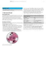
Page 11: ... and MAO blocks are written to a well defined value while all the other function blocks are set to their FF standard default Initial Values Figure 7 Electronic board view After the Cold Start the JDF300 is ready to work displaying the value of MAO_IN1 input 1 with its default Subtag and unit code while the quality status is displayed as textual format Refer to the Block s table at the end of this ...

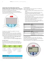
Page 12: ...over with Ex d 2 Attach the LCD display Depending on the mounting position of the field indicator the LCD display may be attached in four different positions This enables 90 or 180 rotations Retighten the housing cover until it is hand tight If necessary refer to the section Securing the housing cover with Ex d Figure 8 Indicator side view with cover open Integral Display Rotation It is possible t...

Page 13: ...o identify the displayed measure Unit code of the displayed measure as a text of 8 characters The user can write the Variable TAG and its unit code of each of the 8 MAO Block inputs Refer to the parameters HMITB_INPUT x TAG and HMITB_INPUT x Unit indexes from 17 to 32 where x goes from 1 to 8 identifying one of the 8 MAO inputs Row 4 displays Diagnostic error code of three digit size plus the NAMU...

Page 14: ...ls could be taken in account The menu submenu name is displayed above in the LCD display The number line of the currently selected menu item is displayed in the upper right of the LCD display A scroll bar is located on the right edge of the LCD display which shows the relative position of the currently selected menu item within the menu Both of the keys 1 and 4 can have various functions The meani...

Page 15: ...events the configuration data from being overwritten by unauthorized users If write lock is enabled the Z and S buttons are disabled When the JDF300 is write locked the lock symbol is displayed in the bottom side of the display However when write lock is enabled it is still possible to read out the configuration data through the HMI local menus or using DD based configuration tools Write lock is a...

Page 16: ...munication or through the S button the Autoscrolling function is enabled While the HMI_IN_SEQUENCE is enabled ON the Z button stops its function until the HMI_IN_SEQUENCE is disabled again After the S button is held down for at least 0 5 seconds when released it enables or disable the automatic scrolling of the MAO inputs If the HMI_IN_SEQUENCE is disabled OFF the S button enable the Auto scrollin...

Page 17: ...o blinks the string Squawk When Squawk is enabled on the display it starts to blink the word Squawk till when the HMITB_SQUAWK parameter is disabled again or till when the user who find the device in the field push any button of the housing or on the display When the Squawk is enabled once still writing in the parameter HMITB_SQUAWK index 37 the display of the selected device starts to blink the s...

Page 18: ...parameters relating the NAMUR NE107 requirements are those with the prefix FD_xxx Each root error is mapped into one of the four NAMUR NE107 classifications Failure Maintenance Out of Specifications and Function Check triggering the transmission of the relating Alarm to the hosts This parameter set is intended to be the minimum required for the Function Block Application associated with the resour...

Page 19: ... The SW4 of the electronics is in ON position enabling the Simulation Bit 6 Device Needs Maintenance Soon NV Mem Burn error Bit 11 Lost NV Data Electronic memory fail Bit 15 Out of Service The Resource Block MODE_BLK_ACTUAL Out of Service Also the Actual mode of all the Funct Blocks is forced to OOS 7 RS_STATE State machine of the function block application 8 TEST_RW Read Write test parameter used...

Page 20: ...he first alert to become active will set the Active Status in the status parameter As soon as the Unreported status is cleared by the alert reporting task another block alert may be reported without clearing the Active Status if the subcode has changed 37 ALARM_SUM The alert status associated to the function block 38 ACK_OPTION 0 Auto Ack Disabled default Selection of whether alarms associated the...

Page 21: ...rer 69 SPECIAL_RESTART Bit 11 AR pre setting After the selection of one or more blocks of this list is written to SPECIAL_RESTART then the operation is really executed writing the command Special Restart in the RB_RESTART All the selected Blocks are configured to a pre defined setting allowing their switching to AUTO Mode PS The Function Blocks must have been previously instantiated into a Functio...

Page 22: ...e display configuration While the Value and Quality Status are received from the selected MAO Input the Subtag and Engineering unit to display together with the value must to be configured inside this block writing in the HMITB_INx_SUBTAG and HMITB_INx_UNIT CODE where x is the number of the input between 1 and 8 There is also the possibility to enable disable each of the 8 inputs into HMITB_IN_ENA...

Page 23: ...rt is generated by any change to the static data 8 BLOCK_ALM The block alarm is used for all configuration hardware and connection failure or system problems in the block The cause of the alert is entered in the sub code field The first alert to become active will set the Active Status in the status parameter As soon as the Unreported status is cleared by the alert reporting task another block ale...

Page 24: ... Number of power cycle 39 TOT_WORK_TIME Counter of how much time the device has been powered on expressed in days hours mins 10 Control Application Process CAP Blocks Multiple Analog Output Function Block MAO Overview The MAO block makes available to the I O subsystem its eight input parameters IN_1 8 This function block keeps the fault state features specified for the AO block It includes option ...

Page 25: ...Bit 0 Other MAO Not Scheduled Bit 1 Configuration Error MAO Channel 0 Uninitialized Bit 15 Out of Service 7 CHANNEL 0 Uninitialized Doesn t allow at the MAO to move out from OOS 1 8 INPUT n selection CHANNEL 1 default 8 IN1 Input 1 Floating Point value Status 9 IN2 Input 2 10 IN3 Input 3 11 IN4 Input 4 12 IN5 Input 5 13 IN6 Input 6 14 IN7 Input 7 15 IN8 Input 8 16 MO_OPTS All set to 0 not used in ...

Page 26: ...Configuration error M080 005 Enable at least one input in the HMITB IN_ENABLED 30 Electronic Memory Fail Memory data corrupted Memory failed F RB Lost NV data F150 030 Electronic should be replaced as soon as possible 31 Electronic NV memory burn fail Configuration data are not well stored in NV memory NV memory defect M RB Device needs maint soon M130 031 Electronis should be replaced when possib...

Page 27: ...er whose time constant is PV_FTIME The value is then shown as the PV which is used in conjunction with the SP in the PID algorithm A PID will not integrate if the limit status of IN is constant A full PV and DV alarm sub function is provided The PV has a status although it is a Contained parameter This status is a copy of IN s status unless IN is good and there is a PV or block alarm The full casc...

Page 28: ...eedback so it must be set properly and never changed while in an automatic mode The setting of the option must also be used in calculating the limit state for BKCAL_OUT The output supports the feed forward algorithm The FF_VAL input brings in an external value which is proportional to some disturbance in the control loop The value is converted to percent of output span using the values of paramete...

Page 29: ...e calculated as a result of the block execution expressed in OUT_SCALE unit code Writeable only if MODE_BLK ACTUAL MAN 10 PV_SCALE The high and low scale values engineering units code and number of digits to the right of the decimal point to be used in displaying the PV parameter and parameters which have the same scaling as PV 11 OUT_SCALE The high and low scale values engineering units code and ...

Page 30: ...T_SCALE Unit Code 28 OUT_HI_LIM Acceptable value OUT_SCALE 10 Expressed in OUT_SCALE Unit Limits the maximum output value 29 OUT_LO_LIM Limits the minimum output value 30 BCAL_HYS 0 to 50 Default 0 5 Expressed as percent of the OUT_SCALE span The amount that the output must change away from its output limit before the limit status is turned off 31 BKCAL_OUT Expressed in PV_SCALE Unit The value and...

Page 31: ...y be reported without clearing the Active Status if the subcode has changed 46 ACK_OPTION Used to set auto acknowledgment of the alarms 47 ALARM_HYS Alarm Hysteresis is the amount the PV must return within the alarm limit before the alarm condition clears 0 or 0 expressed as percent of the OUT_SCALE span default 0 5 48 HI_HI_PRI 0 15 Expressed in OUT_SCALE unit 49 HI_HI_LIM Critical Limit High pro...

Page 32: ...t Mode of the RESOURCE BLOCK to AUTO mode The Block is not scheduled Design the FB Application correctly and download it to the devices The Block cannot be removed from IMAN mode Something wrong in the BKCAL_IN The Status received in input of the BKCAL_IN is BAD Not Connected Configure the link with the downstream block The downstream block is producing a BAD status or Not Invited Check the reason...

Page 33: ...nded to be used in a control path so it does not support control status propagation or back calculation It has no process alarms The block has 5 inputs The first two are dedicated to a range extension function that results in a PV with status reflecting the input in use The remaining three inputs are combined with the PV in a selection of four term math functions that have been found useful in a v...

Page 34: ...uations The equation for each auxiliary input is the following t_i IN_i BIAS_IN_i GAIN_IN_i The flow compensation functions have limits on the amount of compensation applied to the PV to assure graceful degradation if an auxiliary input is unstable The internal limited value is f Equations Algorithm Type Description Function Flow Compensation Linear Used for density compensation of Volume flow OUT...

Page 35: ...ach time a static parameter value S under Storage in the block is changed 2 TAG_DESC The user description of the intended application of the block 3 STRATEGY The strategy field can be used to identify grouping of blocks This data is not checked or processed by the block 4 ALERT_KEY The identification number of the plant unit This information may be used in the host for sorting alarms etc 5 MODE_BL...

Page 36: ...tiplied times IN_3 Bias 27 COMP_HI_LIM The high limit imposed on the PV compensation term Expressed in PV_SCALE Unit Code 28 COMP_LO_LIM The low limit imposed on the PV compensation term Expressed in PV_SCALE Unit Code 29 ARTH_TYPE The identification number of the arithmetic algorithm 1 Flow Compensation Linear 2 Flow Compensation Square Root 3 Flow Compensation Approximate 4 BTU Flow 5 Traditiona...

Page 37: ... configured to use it In this case the Status of the OUT is UNCERTAIN Otherwise the OUT Status id the worst of the inputs used in the calculation after applying the INPUT_OPTS Troubleshooting Problem Possible cause Solution The Block cannot be removed from OOS mode The Target Mode is not set to AUTO Set the Target Mode to AUTO and or remove the OOS The Configuration Error bit is set in the BLOCK_E...

Page 38: ...nfigured and a bad status is passed to one of the inputs Logic is provided for handling uncertain and bad signals in conjunction with configured actions The intended application of this block is to provide control signal selection in the forward path only therefore no back calculation support is provided SELECTED is a second output that indicates which input has been selected by the algorithm Bloc...

Page 39: ...erage was used else set SELECTED to the number of the input with the middle value If SELECT_TYPE is Average compute the average of the remaining inputs and transfer the value to the output of the block Set SELECTED to the number of inputs used in the average Limit Processing The computations to determine high and low limit conditions for the output can be complex They should be done to the best of...

Page 40: ... on the block 9 GRANT_DENY Options for controlling access of host computer and local control panels to operating tuning and alarm parameters of the block 10 STATUS_OPTS Options the user may select to alter the calculation done in a control loop Bit 3 Propagate Fault Forward Enable Disable the propagation of the Status byte from the PRTB in input at the AI to its Output Bit 6 Uncertain if Limited B...

Page 41: ... to Good when the Selected Input Status is Uncertain Uncertain if Manual Mode The Status of the IS_OUT is set to Uncertain when the Mode is set to Manual Troubleshooting Problem Possible cause Solution The Block cannot be removed from OOS mode The Target Mode is not set to AUTO Set the Target Mode to AUTO and or remove the OOS The Configuration Error bit is set in the BLOCK_ERR Set the SELECT_TYPE...

Page 42: ...d Control blocks that are not selected are limited in one direction only determined by the type of selector The value of each BKCAL_SEL_N output is the same as OUT The limits of back calculation outputs corresponding to deselected inputs will be high for a low selector and low for a high selector or one of each for a mid selector Equations With the SEL_TYPE it is possible select the following algo...

Page 43: ...IN Bit 2 Use Uncertain as Good 11 SEL_1 First input value to the selector Expressed in OUT_SCALE Unit 12 SEL_2 Second input value to the selector 13 SEL_3 Third input value to the selector 14 SEL_TYPE Options which the user can select for the block processing of status The available selections are 1 High 2 Low 3 Middle 15 BKCAL_IN The analog input value from another block s BKCAL_OUT output that i...

Page 44: ..._SEL_x output The BKCAL_SEL_x Status of the deselected inputs is set to Not Selected with the appropriate high or low limit set When the CS is in MAN no inputs are selected All the BKCAL_SEL_x status are set to Not Invited and Constant limits with the same value of OUT Troubleshooting Problem Possible cause Solution The Block cannot be removed from OOS mode The Target Mode is not set to AUTO Set t...

Page 45: ... IEC TS 60079 31 1 Cleaning of the painted surface shall only be done in accordance with the manufacturer s instructions Explosion proof field indicator must be either repaired by the manufacturer or approved by a certified expert following repair work Observe the relevant safety precautions before during and after repair work Only disassemble the field indicator to the extent necessary for cleani...

Page 46: ...ust be connected to a supply associated apparatus certified Ex ia The other marking part refers to the protection type used according to relevant EN standards and is valid also for IECEx as detailed in FM Approvals certificate number IECEx FME 18 0004X Ex ia Intrinsic safety IIC Gas group T4 Temperature class of the field indicator corresponding to 135 C max with a Ta from 50 C to 85 C T5 Temperat...

Page 47: ... application Db Equipment Protection Level About the applications this field indicator can be used in Zone 1 Gas classified areas continuous hazard About Dust application JDF300 is suitable for Zone 21 according to the EN 60079 1 as it is shown on the relevant part of the sketches IP code About the degree of protection provided by the enclosure of the field indicator has been certified IP66 IP67 a...

Page 48: ...is field indicator can be used in Zone 2 Gas unlikely infrequent hazard About Dust application JDF300 can be used in Zone 22 unlikely infrequent hazard as it shown on the following skecth Application for field indicator Ex ic tc categories Gc and Dc Application with Gas Zone 2 JDF300 Category 3 G Ex ic Note the field indicator must be connected to a supply with 42V d c max output voltage as above ...

Page 49: ... and IP Protection USA Applicable standards According to FM here is the list of Standards which can assure compliance with Essential Safety Requirements Standard Description 3810 Safety Requirements for Electrical Equipment for Measurement Control and Laboratory Use General Requirements 3600 ANSI ISA 60079 0 Electrical Equipment for use in Hazardous Classified Locations General Requirements ANSI I...

Page 50: ... been certified for the following Class Divisions and Gas groups hazardous classified locations temperature class and types of protection Explosionproof Canada for Class I Division 1 Groups A B C and D hazardous classified locations Class I Zone 1 Ex db IIC T4 Gb as Ex db type of protection Dust ignition proof for Class II III Division 1 Groups E F and G hazardous classified locations as Ex tb typ...

Page 51: ...wing 3KXP000074U0109 Canada Class I Zone 0 Ex ia IIC T6 T4 Ga Class I Division 1 Groups A B C D T6 T4 Class II Division 1 Groups E F G T6 T4 Class III when connected per drawing 3KXP000074U0109 US Class I Division 1 Groups A B C D T4 Class II III Division 1 Groups E F G T4 Class I Zone 1 AEx db IIC T4 Gb Canada Class I Division 1 Groups A B C D T4 Class II III Division 1 Groups E F G T4 Class I Zo...

Page 52: ...ontained therein Any reproduction disclosure to third parties or utilization of its contents in whole or in parts is forbidden without prior written consent of ABB Copyright 2020 ABB All rights reserved 3KXJ000001R4201 ABB Limited Measurement Analytics Howard Road St Neots Cambridgeshire PE19 8EU UK Tel 44 0 870 600 6122 Fax 44 0 1480 213 339 Email enquiries mp uk gb abb com ABB Inc Measurement An...

Reviews: