12
J DF 3 0 0 |
FI EL D I N D I C ATO R | O I/J D F 3 0 0 - EN R E V. B
8 Display
Configuration of the field indicator using
the optional integral LCD with keypad
(menu-controlled)
The integral LCD is connected on the field indicator electronic
board. It can be used to visualize the process measured
variables as well as to configure the display.
In addition, diagnostic information is provided. To access the
functionality of the LCD an activation procedure needs to be
carried out.
The keypad operability doesn’t require any activation
procedure.
Installing/Removing the LCD display
1
Unscrew the housing cover of the communication board/
LCD side.
With an Ex d / Flameproof design, please refer to the
section “Securing the housing cover with Ex d”.
2
Attach the LCD display. Depending on the mounting position
of the field indicator, the LCD display may be attached in four
different positions. This enables ± 90 ° or ± 180 ° rotations.
Retighten the housing cover until it is hand-tight.
If necessary, refer to the section “Securing the housing
cover with Ex d”.
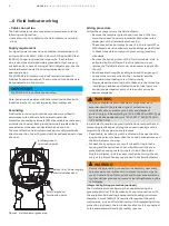
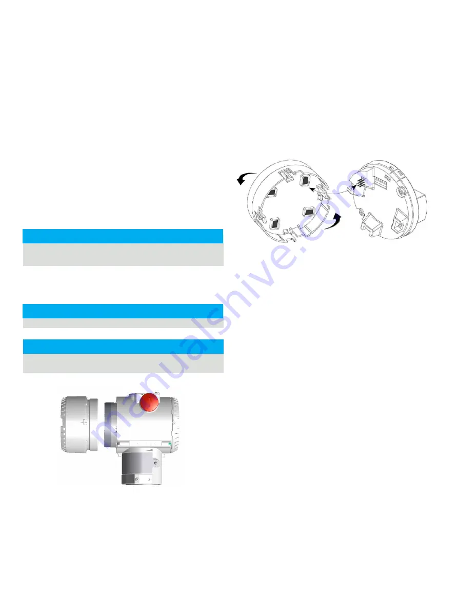
Figure 8 Indicator side view with cover open
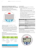
Integral Display Rotation
It is possible to mount the display in four different positions
rotated clockwise or counterclockwise with 90° steps.
To rotate the LCD, simply open the windowed cover (Hazardous
area prescriptions must be respected), pull-out the display
housing from the communication board. Reposition the
LCD connector according to the new desired position. Push
back the LCD module on the communication board. Be sure that
the 4 plastic fixing locks are properly in place.
Figure 9 Integral display plug-in
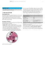
IMPORTANT
IMPORTANT
IMPORTANT

