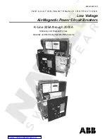
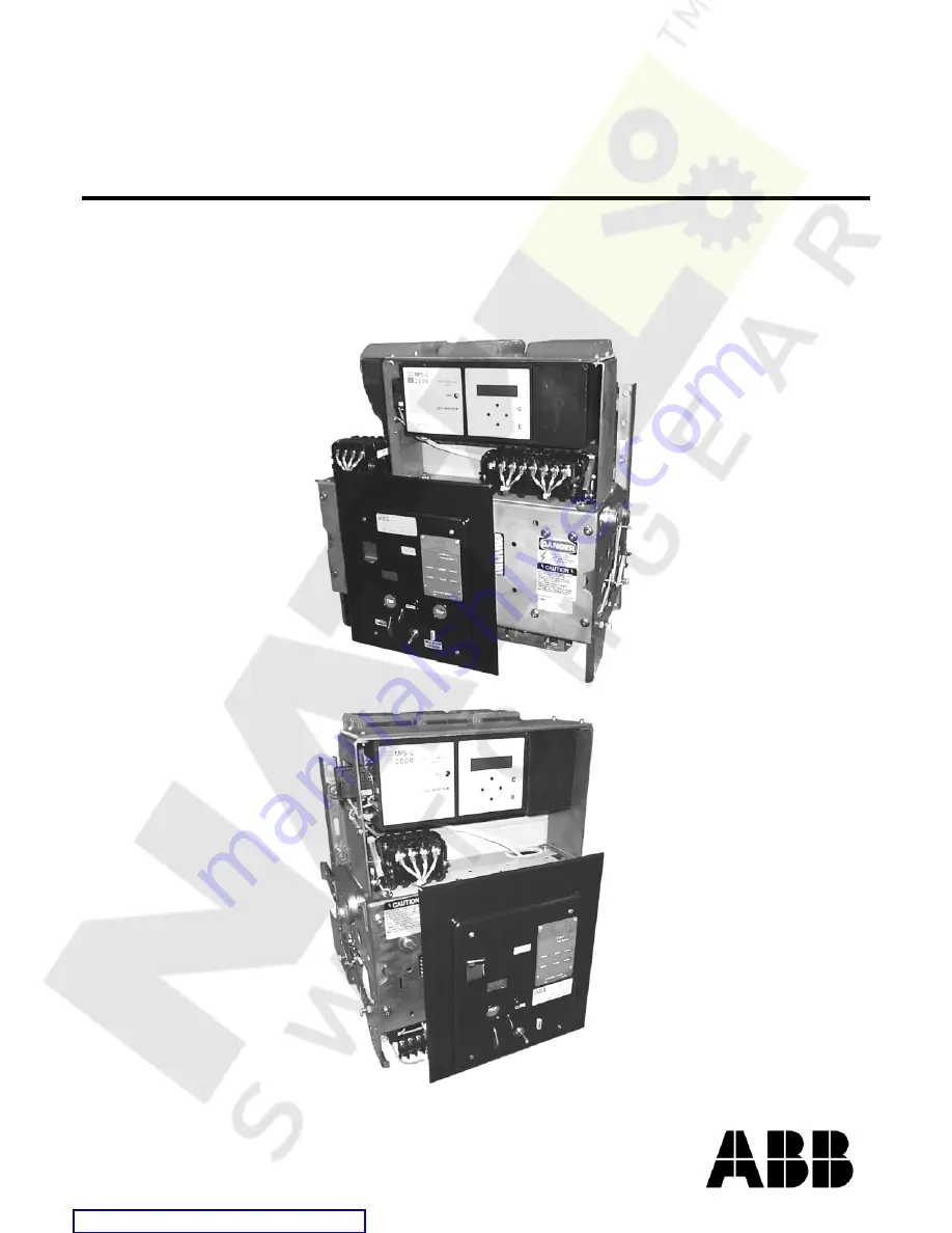
background image


IB 6.1.12.1-1C 


I N S T A L L A T I O N / M A I N T E N A N C E   I N S T R U C T I O N S  

Low Voltage 

Air-Magnetic Power Circuit Breakers 

K-Line 225A through 2000A 

Stationary and Draw-out Frames 

Manually and Electrically Operated Mechanisms 

Courtesy of NationalSwitchgear.com

Summary of Contents for K-Line 1600A

Page 1: ... O N M A I N T E N A N C E I N S T R U C T I O N S Low Voltage Air Magnetic Power Circuit Breakers K Line 225A through 2000A Stationary and Draw out Frames Manually and Electrically Operated Mechanisms Courtesy of NationalSwitchgear com ...

Page 2: ... Close Lever EO 7 Contact Position Indicator 7 Lifting Yoke Optional 7 Locking Hasp 7 Maintenance Handle EO 8 Motor Disconnect Switch EO 8 Nameplate 8 Racking Mechanism 8 Stored Energy Indicator EO 8 Trip Buttons 8 OPERATING DEVICES 9 Auxiliary Switches 9 Control Relay Device 9 Magnetic Latch Device 9 Shunt Trip Device 9 Overcurrent Trip Devices 9 Electromechanical Overcurrent Trip 9 Solid state O...

Page 3: ...ers 16 Lubrication 16 Structural Insulation 17 Setting Adjustments 17 Contact Structure 17 Control Relay Device 20 Close Latch Release Rod Travel 20 Trip Latch Engagement 20 Tripper Bar Travel 20 Shunt Trip Device 21 Magnetic Latch Device 22 Electro Mechanical Overcurrent Trip Device OD 22 Solid state Overcurrent Trip Device 23 Microelectronic Overcurrent Trip Device 23 Operational Checks 23 Draw ...

Page 4: ...every possible contingency to be met in connection with installation operation or maintenance Should further information be desired or should particular problems arise which are not covered sufficiently for the purchaser s purpose the matter should be referred to the nearest District Office Courtesy of NationalSwitchgear com ...

Page 5: ...ARNING Not adhering to these instructions may result in serious injury and equipment damage DANGER Not adhering to these instructions may result in life threatening injury and permanent equipment damage All circuit breakers have been equipped with safety interlock systems that must never be defeated Interference Blocking physically prevents installation of a breaker into an incompatible enclosure ...

Page 6: ...nput Drive Shutter Closed Locking Hasp Manual Close Lever Mechanical Operations Counter Optional Trip Button Mechanical Contact Position Indicator Circuit Breaker Nameplate Close Button Electrical Trip Button Electrical Option Auto Trip Indicator with optional Lockout and optional Alarm Contacts Post Order Service Decal Motor Disconnect Switch Stored Energy Indicator Accessory Lifting Yoke Draw ou...

Page 7: ...ator provides remote indication of an automatic trip event The trip indicator actuates a roller on the alarm switch during an overcurrent trip Resetting the automatic trip indicator also resets the alarm contacts Automatic Trip Lockout Optional Following a fault the lockout places the circuit breaker trip free by holding the tripper bar paddle in the trip position The circuit breaker cannot be clo...

Page 8: ...of the circuit breaker as certified per design Do not exceed these limits The nameplate also lists the circuit breaker model type frame size and serial number Provide the serial number when contacting ABB for information Racking Mechanism Utilize a racking handle as shown in Figure 1b to operate the racking mechanism of draw out circuit breakers The racking mechanism moves a draw out type circuit ...

Page 9: ... the graphed time bands subject to the notes therein The tolerance for a trip event at a pickup setting is Long time 10 Short time 15 Instantaneous 20 Ground 15 not available with OD Refer to Tables B1 B2 B3 and B4 of Appendix B for standard device types testing and applicable time current curve references For non standard trip devices not listed consult ABB Electromechanical Overcurrent Trip Thes...

Page 10: ...PS C and MPSC 2000 units can be tested with the BTSB Bench top Trip Simulator for Breakers both on and off the breaker Tested on the breaker the BTSB can also operate the magnetic latch as part of the fault simulation When testing the MPS C the BTSB interactively guides the user through the test sequence When testing the MPSC 2000 the BTSB runs all tests unassisted and restores the original settin...

Page 11: ...oaded disconnects engage the cubicle stabs Removing a draw out breaker from service 1 Place the motor disconnect switch if equipped in the OFF position to prevent subsequent closing spring recharging after breaker opening Open the breaker 2 Rotate the handle CCW placing the breaker in the TEST position 3 Rack fully CCW into the DISCONNECTED position If the closing springs are charged the automatic...

Page 12: ...d breakers are closed at the end of the charging cycle during the continuous handle motion described in the charging section Opening Operation The loaded contact springs and two charged opening springs provide the energy for opening the circuit breaker Opening is either manual or automatic Manual opening is performed locally with the mechanical push button trip or the optional push button electric...

Page 13: ...the top of the hole as the fulcrum and a screwdriver or rod as a lever depress the hold up latch At the same time pull the operating handle forward enough to engage the slow close latching then work the handle in one stroke to move the contacts through the open to close range WARNING Keep a firm grip of the handle which is loaded with the energy of the mechanism when slow closing 4 Remove the two ...

Page 14: ...ower the circuit breaker so that the positioning pins two on each side of breaker rest in the cut out sections of each rail 4 Remove the lifting yoke and push the circuit breaker toward the compartment The breaker will slide on its positioning pins to the rear of the cut out sections in the rails An additional push will overcome the two cradle latches allowing the circuit breaker to move into the ...

Page 15: ...ment is not required for most devices unless removal of another device so affects it DANGER Beware of electrical hazards Remove a circuit breaker from service CONNECTED before attempting any maintenance activities Draw out circuit breakers must be withdrawn to the TEST position before any operational checks and withdrawn from the cubicle for inspection adjustment or repair Stationary breakers must...

Page 16: ...lugs and terminals are securely fastened Confirm correct wiring with preoperative checks that use the connected device If an electrical malfunction is detected compare the physical wiring configuration against the schematic diagram of Figure A1 of Appendix A Test dielectric integrity with a Withstand Voltage Test as outlined in the Insulation Withstand section Disconnects Inspect the primary disco...

Page 17: ...or damage Glass polyester insulation may be cleaned with a clean cloth and denatured alcohol While cleaning parts avoid getting alcohol on points of lubrication Test the insulation dielectric as described in the Insulation Withstand section Setting Adjustments The breaker control devices utilize self locking hardware that should not be routinely adjusted otherwise the locking feature becomes incre...

Page 18: ...essure by 1 8 revolution CW and recheck the simultaneous make Repeat in increments of about 1 8 revolution for no more than 1 2 revolution of the adjusting stud on the first make pole until the breaker latches closed If for any reason the contact structure is removed from the breaker upon assembly reapply clean NO OX ID A Special to the ends of the contact bushing Torque the nut of the hinge joint...

Page 19: ...re Decrease Figure 6a 225 Ampere Contact Structure Left hand view drawn in the closed position Similar structure to Figure 6b except the moving arc contact member serves as the moving main contact member Notice that the upper terminal is comprised of one stud Contact pressure is established by open air gap A Figure 6b 600 and 800 Ampere Contact Structure Left hand view drawn in the closed position...

Page 20: ...gagement bite and the tripper bar travel are located on the right hand mechanism housing Access the screws from the top of the breaker To adjust the latch engagement proceed as follows WARNING This adjustment is made on a closed breaker Keep hands and tools clear of moving parts while setting the device Furthermore the breaker may trip before the point anticipated 1 If the circuit breaker will not...

Page 21: ... travel by advancing the trip rod CW an additional 3 revolutions K 600S K 800S and K 800M All small frame breakers with electronic trip 1 Locate the device illustrated in Figure 10 on the left side of the mechanism On an open breaker fully reverse CCW as viewed from the hex head the adjustment of the trip rod or at least enough that a closed breaker will not trip with the device armature sealed 2 ...

Page 22: ...th the desired pickup point scribe mark Long time Delay Band Adjustments Turn the delay adjustment screw until the top of the indicator matches the desired delay line Push the armature toward the magnet allowing time for oil in the dashpot to be displaced Release the armature allowing it to reset Check that the long time indicator still matches the calibrated pickup marking Readjust if required an...

Page 23: ...evice No device adjustments are made on MPS MPS C or MPSC 2000 devices Trip settings are set on the unit and only need confirmation See Tables B3 and B4 of Appendix B for applicable time current curves and reference to complete device instruction and testing WARNING Do not disconnect the harness from the trip unit on an energized breaker Current transformers on the breaker poles power the trip uni...

Page 24: ... 5 to 10 seconds and maintain for 1 minute Flashover defines a failed test Testing a Power Shield trip unit 1 Connect all sixteen terminals of the Power Shield trip unit together 2 Apply 500 VAC between the sixteen terminals and metal parts normally grounded ABB does not recommend withstand testing of the MPS MPS C or MPSC 2000 trip units Points of Test Voltage Application On an OPEN circuit break...

Page 25: ...IB 6 1 12 1 1C 2 5 ABB Courtesy of NationalSwitchgear com ...

Page 26: ...Courtesy of NationalSwitchgear com ...

Page 27: ...ease Operating Range Coil Current Recommended Control Fuse Rating V f A A V A A V A A 120 VAC 50 60 Hz 10 4 104 127 0 15 1 5 104 127 6 5 10 240 VAC 50 60 Hz 5 2 208 254 0 075 0 75 208 254 1 15 10 48 VDC 25 10 38 56 0 11 1 26 28 56 3 14 15 125 VDC 10 4 100 140 0 054 0 69 70 140 1 3 10 250 VDC 5 2 200 280 0 026 0 38 140 280 0 65 10 Table A3 Undervoltage Trip Device Operating Conditions Reference IB ...

Page 28: ...ed Y 1 Y contact normally open Y 2 Y contact normally closed LS 1 LS 3 LS contact normally closed when closing springs are discharged LS 2 LS contact normally open when closing springs are discharged Figure A1 Schematic of a Basic Control Circuit for an EO circuit breaker Illustrated for a breaker in the OPEN and SPRINGS DISCHARGED state The basic circuit includes a closing spring charging motor l...

Page 29: ...nical Overcurrent Device Nameplate Rating OD 3 OD 4 OD 5 OD 6 OD 7 OD 8 A AC DC AC DC AC DC 15 9 20 9 9 9 30 9 40 9 9 9 50 9 70 9 9 9 90 9 9 100 9 9 125 9 9 9 9 150 9 9 175 9 9 200 9 9 225 9 9 9 9 250 9 9 300 9 9 350 9 9 400 9 9 9 9 450 9 9 500 9 9 9 600 9 9 9 9 800 9 9 9 9 1000 9 9 9 1200 9 9 1600 9 9 9 9 2000 9 9 9 9 2500 9 Courtesy of NationalSwitchgear com ...

Page 30: ...150 225 200 175 150 225 200 175 150 6 212 40 250 250 4 450 c 400 350 300 250 d 450 c 400 350 300 250 d 3 50 100 600 500 800 600 500 2 30 200 250 250 4 450c 400 350 300 250 d 450c 400 350 300 250 d 3 50 100 800 600 500 800 600 500 2 30 200 1600 1200 1000 1600 1200 1000 1 7 5 200 2500 2000 1 5 0 200 a Maximum allowable resistance for Ag plated devices that are fully loaded at the highest current rat...

Page 31: ...um Allowable Resistancea b Frame Size New or Restored As found Maximum Test Currentc A µΩ µΩ A 225 120 200 100 600 63 100 200 800 63 100 200 1600 28 50 200 2000 24 50 200 a Measure between upper and lower terminals exclusive of the primary disconnects b Double the allowable values for breakers with a Cd plated current path c When testing OD circuit breakers do not inject a test current through the...

Page 32: ...urrent when using a DC equivalent of 0 95ACRMS If measuring device reads ACpeak then obtain an ACRMS reading by dividing ACpeak by 2 b The OD 3 long time delay element has one wide range time delay band All other OD devices with LT delay have three time delay bands Table B2 Standard Solid state Trip Devices Reference IB 6 1 2 7 4 for Power Shield Operating Instructions and Testing Procedure Device...

Page 33: ...eference IB 6 1 1 7 5 for MPS C Operating Instructions and Testing Procedure Reference IB 6 1 2 8 1 for MPS C 2000 Operating Instructions and Testing Procedure Reference IB 6 1 1 7 6 for BTSB Operating Instructions and Testing Procedure Device Elements Overcurrent Device Type LT ST INST GND Time Current Curve MPS C 3 TD 9651 MPS C 4 TD 9651 ST I2 t OUT TD 9653 ST I2 t IN MPS C 5 TD 9651 ST I2 t OU...

Page 34: ... 708392 T07 250 VDC 18006 P20 716799 A02 702250 K07 702250 K02 708392 T08 Current Path Items Item 225 600 800 1600 2000 Primary Disconnects 706777 T01 706777 T03 706777 T11 706777 T15 Secondary Disconnects 703153 K01 4 Contacts Auxiliary Switch Bank 700034 K01 4 Contacts 700038 K01 8 Contacts Upper Base Molding and Stationary Contact Assembly 706784 T01 706784 T03 706784 T05 706784 T06 Moving Cont...

Page 35: ...IB 6 1 12 1 1C 3 5 ABB Notes Courtesy of NationalSwitchgear com ...

Page 36: ...4 Phone 843 413 4700 Fax 843 413 4850 Marketing and Sales 800 338 1585 Post Order Service and Warranty 800 634 7643 Component Sales 800 929 7947 Email dsinfo us abb com ABB Corporate Help Desk 800 626 4999 US Corp Web Site www abb com usa Courtesy of NationalSwitchgear com ...

Reviews: