


IB 6.1.12.1-1C
1
5
ABB
MAINTENANCE
This section provides guidelines applicable under the
normal operating conditions referenced in the
Introductory
section. Where unusual service
conditions exist, ABB presumes that these conditions
were considered at the time of order, the equipment
supplied was designed for the special application, and
an appropriate supplemental maintenance program
had been developed.
Maintenance frequency should be based on factors
that influence the circuit breaker operating condition
over a period of service. The operating condition is
predominantly a function of the circuit duty and the
circuit breaker environment. The merit of a
maintenance schedule should be based on service
records specific to the breaker’s application. ABB
recommends the schedule shown in Table 1 until a
service history is established for the circuit breaker.
Perform maintenance before the number of
operations or time elapsed since the last maintenance
interval, whichever comes first. This schedule may be
altered at the user’s discretion based on actual
performance. On a new circuit breaker, ABB
recommends inspection within the first year of service,
regardless of the number of operations.
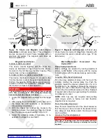
In addition to Table 1, inspect a breaker after short-
circuit interruption as soon as possible. Examine the
arc chutes, the condition of the contacts, and check
the contact pressure before continued service.
ABB recommends circuit breaker refurbishment when
the circuit breaker achieves its designed mechanical
endurance limit or the period of service as shown in
Table 2
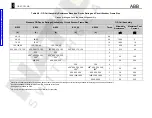
Table 2. Full Refurbishment Schedule
Frame Size
Total
Operations
Service Period
(Years)
225, 600, & 800
12,500
10
1600 & 2000
4000
10
Maintenance programs should consist of inspection,
cleaning, adjustments, and operational checks as
recommended or when affected by other adjustments.
Adjustment is not required for most devices unless
removal of another device so affects it.
DANGER
Beware of electrical hazards. Remove a circuit breaker from
service (CONNECTED) before attempting any maintenance
activities. Draw-out circuit breakers must be withdrawn to the
TEST position before any operational checks and withdrawn
from the cubicle for inspection, adjustment, or repair.
Stationary breakers must be de-energized from the primary
circuit before any operational testing and also from the control
circuit before any inspections or repair.
WARNING
Beware of mechanical hazards. Stay clear of moving parts and
take precaution with the use of tools when operating the circuit
breaker. Notice whether or not the breaker is open or closed by
observing the contact position indicator. Check the charge
status of the closing springs by observing the stored energy
indicator. A charged breaker has the potential to inadvertently
close; likewise, a closed breaker may surprisingly open.
WARNING
Do not work on a draw-out circuit breaker withdrawn on
extended cubicle rails.
To minimize down-time, stock commonly needed
spare parts as suggested in the
Renewal Parts
section.
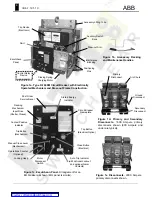
Inspection
Inspect the general condition of the breaker and
enclosure. Initial observations are worth recording for
subsequent troubleshooting and a general feel for the
adequacy of the maintenance program. Inspect the
enclosure floor for broken hardware or fallen parts.
After initial assessment within the enclosure, rack the
circuit breaker out for further inspection.
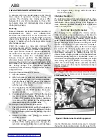
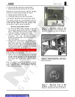
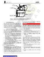
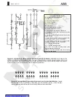
Arc Chutes
The chutes are secured with a screw and a poly-glass
retainer as mounted between the poles. Check the
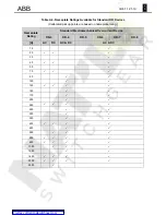
Table 1. Maintenance Schedule Based on Circuit Duty and Circuit Breaker Environment.
Load Current Switching
(Duty
≤
Continuous Current Rating)
Motor Starting or
Capacitor and Reactor
Switching
Clean Environment
Typical Environment
Any Environment
Frame Size
Operations
Years
Operations
Years
Operations
Years
225, 600, & 800
1750
5
1000
3
1000
3
1600
&
2000
500 5 300 3 300 3


