I.L. 41-490H
20
d. The KD-11 relay is purposely biased to produce
current-only contact-closing torque and will open
its right hand contact at a current value of 3 am-
peres or less when T is on maximum tap.
(For .2-4.5 ohm range relay the current only oper-
ation will occur at I
A
= 5
∠
0˚amp and I
B
= 5
∠
120˚
if two phase currents are available.)
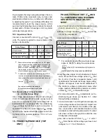
14.5 Maximum Torque Angle Check
a. Use test connection #1.
b. Adjust voltages V
1F-2F
and V
2F-3F
, and current
as per table below:
c. Check maximum torque angle using procedure
described below:
Rotate the phase-shifter to find the angles,
θ
1 and
θ
2, at which the bottom unit contacts just close.
The maximum torque angle
θ
m
for the
three-phase-unit then is
degrees.
The 30 degree correction is made to account for the
fact that test set up angle measurements are made
with reference to phase-to-phase voltage instead of
line-to-neutral voltages. The 3-phase-unit maximum
torque is always referred to as phase-to-neutral.
∆
Test current for other than nominal torque
angle setting should be:
(12)
where
β
= new maximum torque angle.
–————–—| Example 6 |———–———
For
θ
m
= 75
°
, I
test
= 7 amp.
Relay Range
0.2 - 4.5 .75 - 21.2 1.3 - 3.6
V
1F-2F
= V
2F-3F
15
30
30
∆
IT Test Current
13
7
4
Adjust P
3
for Max.
Torque angle,
θ
m
(Nominal if necessary)
60˚
75˚
75˚
θ
1
θ
2
+
(
)
2
-----------------------
30
–
I
θ
I
T
θ
m
sin
β
sin
----------------------
=
if
β
= 60
°
new I
test
=
Increasing P
3
value increases maximum torque an-
gle, and, conversely, decreasing the P
3
value results
in smaller angle.
For lower maximum torque angle adjustment below
70 degrees, for medium and long ranges, and for
short range for settings below 55 degrees move red
lead on fixed phase-shifting resistor R3, to the oppo-
site terminal; where R3 is adjustable resistor use it in
combination with P
3
setting without moving the lead.
14.6 Contact Adjustment
14.6.1 KD-10 Relay
With moving-contact arm against right-hand back-
stop, screw the stationary contact in until it just
touches the moving contact. (Check for contact by
using an indicator lamp.) Then back the left-hand
contact out two-thirds of the turn to give 0.020-inch
gap between contacts.
14.6.2 KD-11 Relay
With moving-contact arm against right-hand side of
the bridge, screw the right-hand contact in to just
touch the moving contact and then continue for one
more complete turn. Adjust left-hand contact as de-
scribed above, except back off one turn to give ap-
proximately 0.031 inch gap.
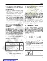
14.7 Spring Restraint
Reconnect for a three-phase fault, Test No. 1 and
set the phase-shifter so that the current lags the volt-
age by:
Adjust the spring so that the current required to close
the left-hand contact is as follows:
90˚
for .2 - 4.5 range
105˚ for .75 - 21.2 and 1.27 - 36.6 ranges
Relay Range
0.2 - 4.5
.75 - 21.2
1.3 - 36.6
V
1F-2F
= V
1FV3F
2.5
10
10
I
trip
KD-10
1.55- 1.65 1.22 - 1.28 .710 - .750
I
trip
KD-11
1.55 - 1.65 1.22 - 1.30 .710 - .765
7
75
°
sin
×
60
°
sin
---------------------------
7.8 amps
=


