7
3.4
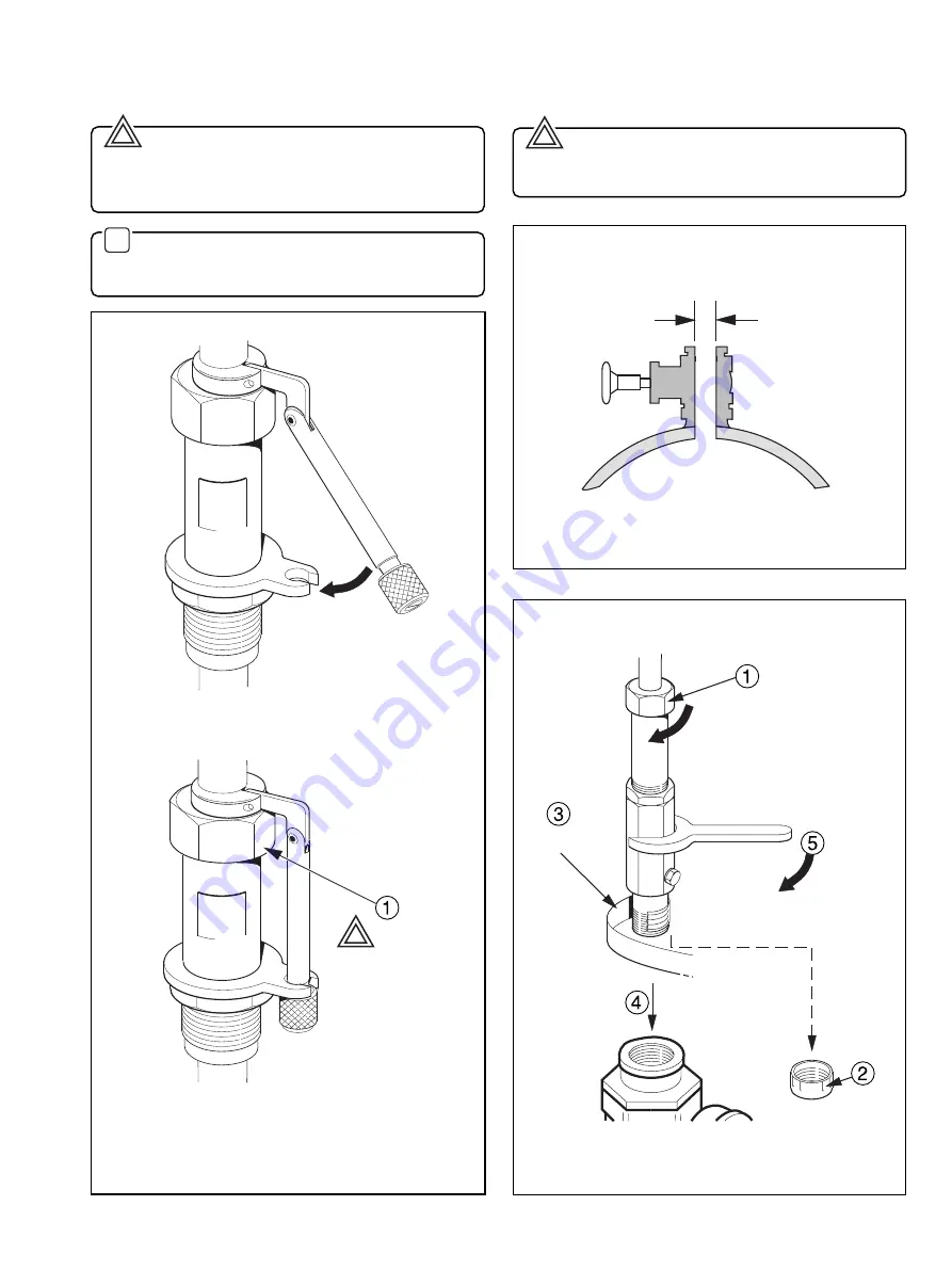
Safety – Fig. 3.9
Warning. The Aquaprobe is provided with a safety
mechanism (see Fig. 3.9) which should be attached to its
securing collar as shown in Fig. 3.9B. This prevents rapid
outward movement by the probe if the nut 1 is released.
✶
Note. To ensure maximum safety, the positioning
collar
MUST
be tightened in place using a 4mm hexagon
key.
3
MECHANICAL INSTALLATION…
3.5
Installing the AquaProbe – Figs. 3.10 and 3.11
Warning. When inserting or removing the
AquaProbe suitable restraining equipment must be used
to prevent the probe being forced out under pressure.
Fig. 3.9 Safety Mechanism
B – Secured
Fig. 3.10 Insertion Bore Clearance
Fig. 3.11 Installing the AquaProbe
Apply
PTFE Tape
Remove
Cap
Tighten
(hand tight only)
Insert Probe
Into Valve
Tighten
Firmly
25mm (1in) Minimum
Clearance
See Text
A – Unsecured
Summary of Contents for Kent-Taylor AquaProbe
Page 22: ...20 NOTES ...


