41-748.31B
12
KLF-1 Loss-of-Field Relay
Repeat above except pass 85% of ICS name-
plate rating current. Contacts should not pickup
and target should not drop.
9.1.1
Routine Maintenance
All contacts should be periodically cleaned. A contact
burnisher Style #182A836H01 is recommended for
this purpose. The use of abrasive material for clean-
ing contacts is not recommended, because of the
danger of embedding small particles in the face of
the soft silver and thus impairing the contacts.
9.2
REPAIR CALIBRATION
A. Autotransformer Check
Autotransformers may be checked for turns ratio
and polarity by applying ac voltage to terminals 4
and 5 and following the procedures outlined
below:
1. Set S
A
and S
C
on tap number 3. Set the “R”
leads of M
A
and M
C
all on 0.0 and discon-
nect the “L” leads. Adjust the voltage for 90
volts. Measure voltage from terminal 5 to the
tap #1 of S
A
. It should be 30 volts (
±
1 volt).
From terminal 5 to tap #2 of S
A
should be 60
volts (
±
1 volt). The same procedure should
be followed for taps #1 and #2 of S
C
.
2.
Set S
A
and S
C
on Tap #1 and adjust the volt-
age at the relay terminals for 100 volts. Mea-
sure voltage drop from terminals 5 to each of
the MA and M
C
taps. This voltage should be
equal to 100 (
±
1 volt) plus the sum of values
between R and tap being measured. Exam-
ple 100 (1 + .03 + .06) = 109 volts (
±
1 volt).
Transformers that have an output different
from nominal by more than 1.0 volt probably
have been damaged and should be replaced.
B. Impedance Unit (Middle Unit) Calibration
Make following tap plate settings:
T
A
= 15.8; T
C
= 5.1
S
C
= S
C
= 1
Make M
A
= M
C
= -.15 settings:
“L” lead should be connected to the “0” insert “R”
lead should be connected to the upper “.06”
insert. (-.03 -.06 -.06 = -.15 between L & R).
For the most accurate calibration preheat relay
for at least an hour by energizing terminals 4, 5,
6, & 7 with 70 volts, phase-to-neutral or terminals
5, 6, 7 with 3-phase 120 volts phase-to-phase
voltages.
The links in the middle tap block should be set
for the + T
C
direction (vertical)
1) Contact Gap Adjustment
The spring type pressure clamp holding the sta-
tionary contact in position should not be loos-
ened to make the necessary gap adjustments.
With moving contact in the opened position, i.e.
against right stop on bridge, screw in stationary
contact until both contacts just make (use neon
light for indication). Then screw the stationary
contact away from the moving contact 1-1/3 turn
for contact gap of .040”.
2) With relay de-energized adjust the restraint
spring so that contact arm just floats.
C. Impedance Characteristic Check
1) Maximum Torque Angle
Adjust the adjustable reactor for about 5 turns
out.
Applying 60 volts ac to terminals 5 and 4 and
passing 4.8 amperes, through the current circuit
turn the phase shifter until the moving contact
opens. Turn the phase shifter back (few degrees)
until contacts close. Note degrees. Continue to
turn the phase shifter until contact opens, then
swing phase shifter back until contact closes
again. Note degrees. The maximum torque angle
should be
(±
1°) computed as follows:
Degrees to Close Contacts at Left +
Degrees to Close Contacts at Right
= 90°
Adjust reactor X
C
until the correct maximum
torque angle is obtained.
2) Sensitivity Adjustment
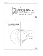
Using the connections of Figure 9 (page 24).
apply 5 volts at 90° leading, to terminals 4 and 5
pass .325 amperes through current circuit termi-
nals 9 and 8. The spiral spring is to be adjusted
2


