10
KM26 |
MAGNETIC LEVEL GAUGE | OI/KM26-EN REV I
MLG configurations
There are several configurations for the KM26. The major
configurations are described in this section.
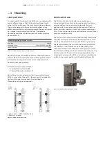
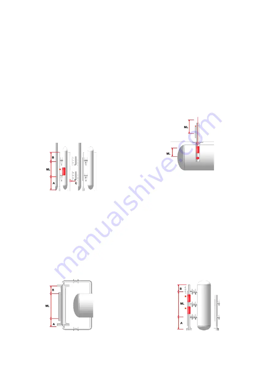
Side Mount
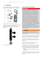
The side mount MLG is referred as the KM26S model which is
the most common configuration. In its simplest configuration
it contains two process connections, a fluid-filled chamber
with flanges and/or caps on the top and bottom, a float, and
a visual indicator. Depending on the tank/vessel height there
can be up to six side process connections.When the liquid
level in a vessel changes, the corresponding level in the MLG
chamber changes as liquid moves through the process
connections located at the top and bottom of the desired
indication range.
Top and Bottom
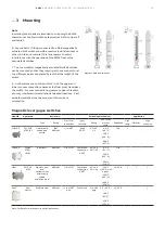
This configuration has process connections at the top and
bottom of the chamber, which are connected to the vessel
through additional piping. The top and bottom mount is
commonly used in spherical-shaped vessels which are filled at
the top and emptied from the bottom of the vessel. The
chamber usually spans the entire height of the vessel and
does not require additional space above the vessel which can
be used in tight plant layouts.
Top Mount
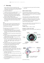
The top mount MLG is also known as the KM26T which is
commonly used for sumps and underground tanks that do
not have side connection access. In its simplest form, a top
mount consists of a chamber with a single flange at the
bottom and a cap at the top. A float assembly hangs below
the chamber into the liquid via a guide rod. The float
assembly consists of a magnet at the top of a guide rod and a
float at the bottom. As the float itself does not contain any
magnet in this configuration, this is also used in applications
where the liquid contains magnetic particles. A stilling well,
can also be used within the vessel to prevent bending of the
rod during maintenance, installation, agitation, or when
turbulence or flow may be present in the tank during
operation.
Dual Level
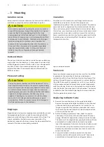
In tanks containing two or more liquids, the KM26 MLGs are
able to measure the interface level between two liquids.The
chamber is capable of housing two floats simultaneously. The
interface float is sized and weighted so that it sinks through
the upper liquid layer and floats on the lower liquid. This
allows the magnets to position precisely at the point of
interface. The other float is weighted to operate at the
specific gravity of the upper liquid, measuring the total level.
For these kind of applications, its always recommended to
have at least three side process connections to ensure reliable
interface measurement. In this case, shuttle indication is
required for proper operation. Shuttle 1 is magnetically
coupled to float 1 and shuttle 2 is magnetically coupled to
float 2.
Other Configurations
KM26 is offered in other configurations like top and side, side
and bottom.
. . . 3 Mounting
Figure 7 - side mount configuration
Figure 8 - top and bottom configuration
Figure 10 - dual level configuration
Figure 9 - top mount configuration

