background image

GLA531 Series LGR-ICOS™ Gas Analyzer

Operating Manual

3KXG165002R4201_2021_04

ABB PROPRIETARY INFORMATION

7

2 General Safety

The following pages provide important safety precautions. Before starting repairs or hardware-related work on the
analyzer, read the safety information in this section.

Before opening the analyzer door, be sure that the area is safe. Contact the local Safety

Department to ensure that all safety guidelines, regulations, and procedures are followed. This
includes obtaining the proper work permits and consulting the

Material Safety Data Sheets for

safety requirements.
Before working on the analyzer, be prepared to work correctly with lethal voltages, infrared light

sources, hazardous gases, and hot surfaces.
Wear protective clothing and use protective equipment appropriate for the specific job.
When working on the analyzer, there is a possibility of exposure to hazardous samples as well as
nitrogen. Although nitrogen is an inert gas, it does not support human life. All appropriate

precautions and care should be taken.
Ensure that there is adequate ventilation while work is being done on the analyzer.
Because the actual configuration of the analyzer depends on the application, this manual cannot

address all of the associated safety problems. It is the responsibility of the user to comply with all

applicable safety guidelines, regulations and procedures.

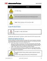
Refer to Table 1 for descriptions of the related safety symbols in this document.

Symbols

The following symbols may be used in the documentation or on the analyzer:

Table 1  Documentation Safety Symbols

Symbols

Meaning

NOTE or

IMPORTANT!

Emphasizes facts and conditions important to analyzer operation.

WARNING!

General warning or caution. Gives general safety information that must be followed to
avoid hazardous conditions.

WARNING!

Laser warning: potential laser hazards

Summary of Contents for LGR-ICOS GLA531 Series

Page 1: ... Series LGR ICOSTM Gas Analyzer Operating Manual ABB Inc Measurement Analytics 3400 rue Pierre Ardouin Quebec Quebec G1P 0B2 Canada Tel 1 800 858 3847 North America Tel 1 418 877 2944 Worldwide Fax 1 418 877 2834 abb com analytical ...

Page 2: ...er Hazards 13 Fire Safety Provisions 14 WEEE Directive 16 3 Features and Theory of ICOS 17 Main Features 17 Theory of Operation 17 LGR s OA ICOS 19 4 User Interface Operation 20 Control Bar 20 Display 21 Numeric Display 21 Spectrum Display 22 Time chart Display 23 Alarm Status Display 24 Rate Button 25 File Button 25 File Transfer 26 Setup Button 27 Time Files 28 Calibration 30 Laser Adjust 31 4 2...

Page 3: ...verter 56 DC DC Voltage Converter 56 Temperature Controller 57 DC Solid State Relay 57 PC104 Computer Stack and Hard Drive 58 4 20 mA Signal Isolators 59 Modbus TCP 59 Two Port Solenoid Driver Board 62 Exhaust Pump 63 Inlet Solenoid Valve 64 PWM Pressure Controller 64 EPC Valve 64 8 Preventive Maintenance 65 Yearly Maintenance 65 Five Year Maintenance 65 Fifteen Year Parts Replacement 66 9 Basic T...

Page 4: ...this document without obligation to notify any person or organization of such changes Every effort has been made to ensure that the information contained in this document is current and accurate However no guarantee is given or implied that the document is error free or that the information is accurate Patent LGR ICOS TM Gas Analyzer technology is protected by patents 7 468 797 6 839 140 6 795 190...

Page 5: ...ct the ABB office that serves your geographical area or the address indicated below ABB Inc Measurement Analytics 3400 rue Pierre Ardouin Quebec Quebec G1P 0B2 Canada Tel 1 800 858 3847 North America Tel 1 418 877 2944 Worldwide Fax 1 418 877 2834 Please contact icos support ca abb com and your local sales representative for more details IMPORTANT Please be prepared to provide the serial number or...

Page 6: ... for references 3KXG165002R4401 Commissioning Instructions 3KXG165002R4201 Operating Instructions this document ABB GLA531 Series LGR ICOS Gas Analyzer offer three types of packaging configurations for different installation locations GLA531 Gas Analyzer with X Purge Protection System purged and pressurized safety enclosure for flammable gas and fire hazards normally specified for Class I Division...

Page 7: ...working on the analyzer there is a possibility of exposure to hazardous samples as well as nitrogen Although nitrogen is an inert gas it does not support human life All appropriate precautions and care should be taken Ensure that there is adequate ventilation while work is being done on the analyzer Because the actual configuration of the analyzer depends on the application this manual cannot addr...

Page 8: ...ondition occurs the internal fuse protects the analyzer and disconnects the power line from the incoming power source The AC powered analyzer is protected by a 5 A fuse in the power entry module located at the upper right hand corner inside the analyzer enclosure There are two high voltage potentials operating above 30 volts RMS inside the enclosure the AC power entry module with the 5 A fuse and ...

Page 9: ...C 61010 1 NFPA 496 NEMA 250 UL 1203 C22 2 No 30 UL 913 C22 2 No 157 UL 60079 0 UL 60079 1 UL 60079 2 UL 60079 11 NEC and CEC 61010 1 NFPA 496 NEMA 250 ISA 12 12 01 UL 60079 0 UL 60079 2 UL 60079 15 II 2G Ex db ib pxb IIB H2 T4 Gb 20 C Ta 50C IP54 ATEX Zone 1 or 2 2014 34 EU ATEX Directive EN 60079 0 EN 60079 1 EN 60079 2 EN 60079 11 EN 61010 EN 61010 2 101 Laser Safety EN 60825 1 2004 108 EC EMC D...

Page 10: ...ations the General Purpose configuration is offered without the protection system for fire hazards It is a simplified product packaging for use in non flammable environments where sample gases are not flammable This General Purpose analyzer complies with European CE Directives and 21 CFR Laser Safety Regulations as listed above in Table 2 Figure 1 Example of a Certification Plate for an Analyzer w...

Page 11: ...rnal pressurization 2 continuously dilute the atmosphere inside the enclosure to prevent any ignitions and 3 prevent fire and explosion hazards Do not bypass any safety procedures when the analyzer is extracting flammable gas or operating in a flammable gas environment DANGER Bypassing the internal pressure switch and opening the front panel during analyzer operations may cause serious accidents a...

Page 12: ...ND PRESSURIZING WHEN USED IN HAZARDOUS LOCATIONS IT MUST NOT BE PUT INTO USE WITHOUT SPECIAL PERMISSION FROM THE INSPECTION AUTHORITY HAVING JURISDICTION WHEN USED IN HAZARDOUS LOCATIONS Burn Hazards The analyzer is designed to receive high temperature gas up to 105 C at the inlet gas bulkhead The ICOS Module is heated and its internal temperature is maintained during normal operations If controll...

Page 13: ...the ICOS Module and not accessible during normal operations Removing the laser enclosure or cover automatically triggers a safety interlock and shuts down the lasers refer to Figure 3 Laser warning labels are on the ICOS Module enclosure covering the laser s Lasers in the ICOS Module are not field serviceable If a laser fails in the field the entire ICOS Module assembly must be replaced Only one c...

Page 14: ... these precautions when dealing with flammable chemicals Keep all chemical containers away from heat sparks and open flames Only apply on grounded equipment or components Use non sparking tools when in contact with the chemical Store in a cool dry well ventilated place away from incompatible materials If a spill occurs Make sure all handling equipment is electrically grounded Mop or wipe up then p...

Page 15: ...e internal right side panel next to the AC power terminal block and the AC power entry module Figure 7 Laser Radiation Label These labels are located on the ICOS Module covers see Figure 3 Figure 8 Burn Hazard Label This label is located on the ICOS Module cover Figure 9 Fire Hazard Label Warning for the cleaning solvents used for cleaning the ICOS optical mirror ...

Page 16: ...ic Equipment or relevant national laws for example ElektroG in Germany The product must be disposed of at a specialized recycling facility Do not use municipal garbage collection points According to the WEEE Directive 2002 96 EC only products used in private applications may be disposed of at municipal garbage facilities Proper disposal prevents negative effects on people and the environment and s...

Page 17: ...installations which require robust operations and minimal maintenance Flexible configurations which can be customized for various types of background gases and unique requirements Fast response measurements with a refresh rate of less than 15 seconds High accuracy and high precision measurements without requiring frequent calibrations Large HMI screen with Touchscreen control Figure 10 GLA531 Seri...

Page 18: ...esolution absorption spectra may be recorded by tuning the laser wavelength over the probed feature Integration of the measured spectra with the measured values of Gas temperature Gas pressure Path length Line strength of the probed transition allows calculations to determine the mole fraction directly from the relation Equation 3 This equation determines gas concentrations even in hostile environ...

Page 19: ...ffective optical path length is 2500 meters Because the path length depends only on optical losses in the cavity and not on a unique beam trajectory like conventional multi pass cells or cavity ring down systems the optical alignment is very robust allowing for reliable operation in the field The effective optical path length is determined routinely by simply switching the laser off and measuring ...

Page 20: ... Control Bar shown in Figure 14 and Figure 15 lets you select the type of screen to display When the analyzer first starts you can only access the displays and cannot make any changes including shutting down the analyzer until you log in To log in click the Security button far left and enter username and password credentials Once logged in new menu options are available as shown in Figure 15 The s...

Page 21: ...ou select the desired screen Numeric Figure 16 Spectrum Figure 17 Time chart Figure 18 Alarm Status Figure 19 Numeric Display Numeric display is the simplest screen for reading the measurements of gas concentrations The sample gas es measured are in percent parts per million ppm or possibly in parts per billion ppb Figure 16 is an example of a numeric display that shows measurements of four differ...

Page 22: ...f the spectroscopy measurements Laser signal strength defined as transmitted intensity level on the Detector Voltage chart top Detected light absorptions of the targeted gases shown as small dips on the Detector Voltage chart Absorbance signal intensity of the targeted gases shown as peaks on the Absorbance chart bottom Laser frequency linelock at the center of each absorbance window Figure 17 Spe...

Page 23: ...y The Time chart display shown in Figure 18 indicates recorded gas concentrations plotted in time Each point is displayed at an interval rate adjustable by changing the sampling rate of the measurements see Figure 20 The solid black line on the plot is a running average of the last 10 data points Figure 18 Time chart Display ...

Page 24: ...atus The status uses traffic light color indication Green indicates no problem Yellow indicates the analyzer is out of spec or maintenance is soon required Red indicates there is a problem and maintenance is immediately required Error messages for each alarm can be displayed by selecting the relevant alarm button after the button is selected a pop up window appears displaying the messages Figure 1...

Page 25: ...ive of past files The following is displayed yyyy mm dd active data measurement file archive folder of past measurement data points Whenever the analyzer application software is launched the analyzer automatically creates a file name to save the measured data New file names are automatically generated every 24 hours The file name is set in the following order The first six characters represent the...

Page 26: ... USB bulkhead port may be installed Figure 21 USB Special Dongle Ex d Flash Drive for C1D2 or Zone 2 The USB Flash Drive must be in a Fat32 format Format the USB memory accordingly before using to transfer data files from the analyzer hard disk drive STEP 1 Install the USB dongle into the live disconnect bulkhead STEP 2 On the Control Bar select Files to access the File Transfer screen shown in Fi...

Page 27: ...he Control Bar to access the Setup screen shown in Figure 23 The Time Files screen is displayed by default Selection tabs in the Setup screen are Time Files set time and file format Calibration single point calibration using a known reference standard Laser Adjust manually fine tune laser wavelength for goodness of fit GOF if necessary 4 20 mA set the scale for concentration to mA conversion Servi...

Page 28: ... local area network LAN server or NTP Server box This screen also provides LAN connection information between the analyzer and the customer network to which it is connected Use the Clock area to adjust the current time and date for the analyzer see Figure 24 The time zone and daylight savings enable disable feature are also set on this screen Available time stamp formats are listed in Table 3 belo...

Page 29: ...Parameters Table 3 Time Stamp Formats Time Stamp Name Format Absolute Local American mm dd yyyy hh mm ss sss Absolute Local European dd mm yyyy hh mm ss sss Absolute GMT American mm dd yyyy hh mm ss sss Absolute GMT European dd mm yyyy hh mm ss sss Relative Seconds After Power On ssssss sss Relative Seconds in Hours Minutes Seconds hh mm ss sss ...

Page 30: ...the calibration gas bottle to the analyzer inlet line Make sure the gas inlet pressure is below 7 25 psig or less than 0 5 barg STEP 1 Click Setup then the Calibration tab STEP 2 Check the Calibrate box in the Reference Gas Settings pane STEP 3 Enter the gas concentration using the arrow keys in the traceable certified bottle gas menu below the Calibrate box The gas concentration is the known valu...

Page 31: ... keyboard appears as shown in Figure 27 to change the laser operating frequency STEP 4 Adjust the Laser A Frequency Offset using the arrow buttons Shift the target absorption line to the center of the absorption peak STEP 5 Click the carriage return button to accept the new value STEP 6 If Laser B is installed repeat STEP 3 through STEP 5 but for Laser B STEP 7 Uncheck the Disable Automatic Freque...

Page 32: ...4 20 mA screen to set the 4 20 mA output range corresponding to the measured gas concentration Depending on the analyzer model there are up to four channels of gas concentrations To set the range STEP 1 Click Setup then the 4 20 mA tab STEP 2 Enter the maximum value in the gas concentration range for each channel as shown in Figure 28 STEP 3 Click Close to exit the 4 20 mA screen ...

Page 33: ...Figure 28 4 20 mA Analog Output Adjustment Service Screen The Service screen is password protected and only accessible to ABB trained field service personnel WARNING Only authorized personnel may open the analyzer to perform internal maintenance Follow the Lockout tagout procedure when servicing the analyzer ...

Page 34: ...s LGR ICOS Gas Analyzer Shutting Down the Analyzer To properly shut down the analyzer perform a soft shutdown by first selecting the Exit button on the Control Bar When the dialog box appears with the question Do you wish to shutdown see Figure 29 select OK Figure 29 Shut Down Analyzer ...

Page 35: ...is limited to 100 meters per TIA EIA 568 5 A If longer runs are required use active hardware such as repeaters or switches as necessary See Table 4 below for cable installation guidelines For 100BaseTX networking 100 MHz bandwidth Cat 5 cables with RJ 45 connections are sufficient For 10GBASE T 10 Gigabit Ethernet Cat 6 cables are required for improved performance to 250 MHz bandwidth Table 4 RJ 4...

Page 36: ...ll o Disable the Ethernet port o Not attempt another DHCP request until the analyzer is restarted When the above conditions are met the data directory can be accessed using a Windows computer on the same LAN To access the Windows Share Drive STEP 1 Select Start à Run then type YYMMxxxxxxxx Instrument Serial Number STEP 2 Press Enter After the communication link is established a Windows Share Drive...

Page 37: ...alue matches the number set in the Setup à 4 20 mA screen as shown in Figure 28 Real time warning and alarm status signals are also conversions from the single ended 0 to 5 V DC analog signals 0 volt is equal to 4 mA and 5 volts is equal to 20 mA Refer to Table 8 and Table 9 When connecting to the device using the Modbus TCP Protocol refer to Table 6 for a list of parameters For additional informa...

Page 38: ...A Channel and Channel Name Register Type Corresponding 4 20 mA Channel Channel Name 300001 Integer 32767 FS 5 Temperature Warning Alarm 300002 Integer 32767 FS 6 Analyzer Warning Alarm 300003 Integer 32767 FS 1 Gas 1 Concentration 300004 Integer 32767 FS 2 Gas 2 Concentration 300005 Integer 32767 FS 3 Gas 3 Concentration 300006 Integer 32767 FS 4 Gas 4 Concentration 300009 Scaling Value Hi float L...

Page 39: ...ctions on the interface plate CH1 CH2 CH3 and CH4 are the connection points for the 4 20 mA Gas Concentrations Signal wirings see Figure 31 Figure 31 Gas Concentration Screw Terminal Connections The warning alarm signals are ported out through the terminal block for the analyzer warning alarm as shown in Figure 32 Two single ended connections CH5 and CH6 are the connection points for the 4 20 mA w...

Page 40: ...Alarm 9 0 1 Inlet Tubing temperature Inlet tubing temperature is too high or too low Alarm 10 0 1 Analyzer temperature Ambient temperature is outside of alarm set point range Warning 12 0 1 Cavity temperature Cavity temperature is above or below normal Warning 13 0 1 Expansion temperature Expansion chamber temperature is above or below normal Warning 14 0 1 Bulkhead temperature Only on Bulkhead op...

Page 41: ...m 10 0 1 Maintenance Maintenance is needed on system now Warning 12 0 1 Data Health A B Laser A and or B goodness of fit is not optimal Warning 13 0 1 Pressure Pressure is noisy Warning 14 0 1 HD Space HD space is low Warning 15 0 1 Mirror Health A B Mirror health is degrading clean mirrors soon Warning 16 0 1 Linelock A B Laser A and or B peak position is moving very fast Warning 17 0 1 Signal Po...

Page 42: ...trogen filled enclosure In this case the protection system only requires a minimal flow of nitrogen for maintaining an overpressure inside the enclosure as a leakage compensating flow of protective gas The flow rate of N2 mainly depends on the leak rate of the enclosure itself Flammability limits of gases are most commonly expressed in terms of volume percentage Vol at 25 o C and atmospheric press...

Page 43: ...essures and enclosure overpressure settings for the analyzers are listed in Table 10 If there is a large leak of flammable gas inside an enclosure the purge air flow rate must be sufficient to dilute the maximum intake of the flammable gas below 25 of its lower flammability limit LFL The ABB GLA531 Series LGR ICOS Gas Analyzer offers two types of protection systems Both are certified designs for i...

Page 44: ...Operating Manual 3KXG165002R4201_2021_04 ABB PROPRIETARY INFORMATION 44 GLA531 Series LGR ICOS Gas Analyzer Figure 33 GLA531 Series Configuration Comparison Z Purge Type Left and X Purge Type Right ...

Page 45: ... ü The circuit diagrams in Figure 35 CDA purge and Figure 37 N2 purge and the purge flow diagrams in Figure 36 CDA purge and Figure 38 N2 purge illustrate the design of the pressurization system and the power interlock of X Purge type ü For electrical wiring connections refer to the Commissioning Instructions document 3KXG165002R4401 Figure 34 Enclosure Features for X Purge Type Protection System ...

Page 46: ...4201_2021_04 ABB PROPRIETARY INFORMATION 46 GLA531 Series LGR ICOS Gas Analyzer Figure 35 X Purge CDA Controller Circuit Diagram for Power Interlock Figure 36 X Purge CDA Flow Diagram for Pressurization System and Power Interlock ...

Page 47: ...R4201_2021_04 ABB PROPRIETARY INFORMATION 47 GLA531 Series LGR ICOS Gas Analyzer Figure 37 X Purge N2 Controller Circuit Diagram for Power Interlock Figure 38 X Purge N2 Flow Diagram for Pressurization System and Power Interlock ...

Page 48: ...lectrical power is applied to the analyzer This time interval is indicated on the certification plate of the analyzer see Figure 1 Because this automatic timer is a safety feature it cannot be changed or bypassed Whenever a failure is detected hard RESET of the timer must be done by cycling the primary power turn off main power and the countdown of the time interval must start from the beginning N...

Page 49: ...no explosion proof housing above the enclosure Z type analyzers have the options to be powered with AC or 24 V DC For electrical wiring connections refer to the Commissioning Instructions document 3KXG165002R4401 The circuit diagrams in Figure 39 CDA purge and Figure 41 N2 purge and the purge flow diagrams in Figure 40 CDA purge and Figure 42 N2 purge illustrate the design of the Z type simple pre...

Page 50: ...02R4201_2021_04 ABB PROPRIETARY INFORMATION 50 GLA531 Series LGR ICOS Gas Analyzer Figure 39 Z Purge CDA Circuit Diagram for Simple Pressurization and Alarm Figure 40 Z Purge CDA Flow Diagram for Simple Pressurization and Alarm ...

Page 51: ...GLA531 Series LGR ICOS Gas Analyzer Operating Manual 3KXG165002R4201_2021_04 ABB PROPRIETARY INFORMATION 51 Figure 41 Z Purge N2 Circuit Diagram for Simple Pressurization and Alarm ...

Page 52: ...power to the analyzer WARNING It is the responsibility of the plant operator to maintain safe operations of the analyzer Proper operations of the analyzer must always be followed Electrical power to the analyzer must not be restored after the enclosure is opened until the enclosure has been purged for 18 2 minutes for CDA purge or 36 4 minutes for N2 purge at the specified flow rate Do not use ana...

Page 53: ...5002R4201_2021_04 ABB PROPRIETARY INFORMATION 53 DANGER Failure to maintain the protective enclosure for keeping the sufficient Lower Flammability Limit LFL during analyzer operations may cause serious injury or death from unexpected fire and explosion hazards ...

Page 54: ...ended field repairs are replacing components and performing routine maintenance for worn out parts Personnel not trained in servicing the analyzer should not perform maintenance or repair Figure 43 Analyzer Hardware Layout WARNING Only authorized personnel may perform repairs of the internal hardware Follow the Lockout tagout procedure when servicing the analyzer It is recommended that ABB field s...

Page 55: ...e Controller PC200 950 0000 9010 0000 14 Electronic Proportional Control EPC Valve 950 0000 9013 0000 15 ICOS Mirror Flange Assembly HP Dynamic with PZT 950 0000 9028 0000 16 ICOS Mirror Flange Assembly HP Static 950 0000 9034 0000 17 Pressure Gauge 3 PSIA 950 0000 9011 0000 18 TH Amp ICOS Gas Heat Sensor 950 0000 9021 0000 19 Thermistor Assembly Ambient Heat Sensor 950 0000 9029 0000 20 Thermocou...

Page 56: ...right corner of the enclosure When the instrument is operating properly the DC OK green LED illuminates Figure 44 AC DC Power Supply Converter DC DC Voltage Converter The DC to DC voltage converter takes the main 24 V DC from the AC DC power supply and converts it into multiple rails of DC outputs Each DC voltage output wire is color coded as listed in Table 14 below Table 14 Wire Color to DC Volt...

Page 57: ...hermocouple T C input It has a single voltage output to control a DC solid state relay as shown in Figure 47 Figure 46 Temperature Controller DC Solid State Relay DC solid state relays SSR inside the ICOS Module switch the heaters on and off and turn on the exhaust pump The SSR for the heaters receive their enable disable commands from the temperature controllers The SSR for the exhaust pump recei...

Page 58: ...le and digital signal processing board at the bottom This three board stack is a one unit replacement assembly The hard drive contains LGR ICOS TM operating source code and measurement data Maintenance is required when the amount of data exceeds capacity It is recommended to periodically compress and archive files saved in the hard drive to another storage location Figure 48 depicts the PC104 comp...

Page 59: ...ter Stack Refer to Table 16 and Table 17 for the conversion values between the voltage signals and the mA signal outputs The 4 20 mA Signal Isolator can also transmit the analyzer health status 20 mA for healthy status and 4 mA for serious problems Table 16 and Table 17 list warning and alarm descriptions Figure 49 2 Channel 4 20 mA Analog Signal Isolator Modbus TCP The Modbus unit provides digita...

Page 60: ... AI0 Channel 5 Return AI0 Channel 6 Signal AI1 Channel 6 Return AI1 Channel 1 Signal AI2 Channel 1 Return AI2 Channel 2 Signal AI3 Channel 2 Return AI3 Channel 3 Signal AI4 Channel 3 Return AI4 Channel 4 Signal AI5 Channel 4 Return AI5 The Channel 5 and 6 screw terminals on the analyzer interface plate provide a 4 20 mA output signal for error reporting These channels are the equivalents to AI0 AI...

Page 61: ...ure is too high or too low Alarm 9 0 1 1 56 Inlet tubing temperature is too high or too low Alarm 10 0 1 1 875 Ambient temperature is outside of alarm set point range Warning 12 0 1 2 5 Cavity temperature is above or below normal Warning 13 0 1 2 812 Expansion chamber temperature is above or below normal Warning 14 0 1 3 125 Bulkhead temperature is above or below normal this is a tool option Warni...

Page 62: ...eeded on system now Warning 12 0 1 2 5 Laser A and or B goodness of fit is not optimal Warning 13 0 1 2 812 Pressure is noisy Warning 14 0 1 3 125 HD Space is low Warning 15 0 1 3 437 Mirror health is degrading clean mirrors soon Warning 16 0 1 3 75 Laser A and or B peak position is moving very fast Warning 17 0 1 4 06 Laser A and or B power is degrading contact customer support soon Warning 18 0 ...

Page 63: ...exhaust pump is a customized dual head diaphragm vacuum pump Although it is a robust pump the diaphragms wear out eventually and require regular replacements It is recommended to replace both diaphragms every year Control for the exhaust pump comes from the two port solenoid driver board on the second channel through a dedicated SSR Figure 52 Dual Head Diaphragm Vacuum Pump with Fittings ...

Page 64: ...d driver board on the first channel Figure 53 Inlet Solenoid Valve Assembly PWM Pressure Controller The gas pressure control of the analyzer is a pulse width modulated PWM electronic controller which works together with an electronic proportional control EPC valve Figure 54 PWM Pressure Controller EPC Valve An EPC valve is a dynamic adjustment for maintaining a target pressure inside the ICOS cell...

Page 65: ...vailable and includes a pump rebuild kit Inspect the condition of the ICOS mirrors If the mirrors are in good condition no cleaning is necessary Inspect the condition of the hard drive It is recommended to move the old data files to an archive storage location regularly because the oldest data are discarded when the hard drive is full NOTE Dirty mirrors are usually caused by contaminants in the sa...

Page 66: ...ly Pressure controller 2 microns filter 2 pcs Purge override replacement keys 2 pcs 64GB Solid State HD with analyzer software installed and file system set up NOTE Hard drive replacement requires the analyzer s serial or order number for loading the suitable operating system and program codes of the specific analyzer It is not advisable to delete or discard all data from the old hard drive Keep t...

Page 67: ...Operating Manual 3KXG165002R4201_2021_04 ABB PROPRIETARY INFORMATION 67 GLA531 Series LGR ICOS Gas Analyzer ...

Page 68: ...h equilibrium temperature Operating outside of this specified temperature range may produce errors in the measurements If the ambient temperature is within specification contact ABB Service and report which heater is in the warning alarm state to receive further instructions Gas Pressure The analyzer performance is optimized and calibrated at a specific pressure Noise in the pressure directly affe...

Page 69: ...inlet filter thin deposits of contaminants may accumulate on these mirrors over time and the mirror reflectivity decreases Reduction in reflectivity directly affects the effective path length and therefore instrument precision The ring down time is the time constant for the light intensity to decay as it leaves the cavity Laser power and mirror reflectivity issues are reported on the Alarm Status ...

Page 70: ...ay be categorized by which function fails Based on the functional failures the specific hardware can be pin pointed and replaced Table 19 below provides basic guidelines for finding the possible failed components WARNING Repairs and maintenance must be performed by trained personnel who have successfully completed the maintenance course on the analyzer Always follow the Lockout tagout procedure wh...

Page 71: ... Reading on HMI Control Bar Measurement drift or error Display wrong temperature ICOS TH Amp heat sensor assembly Pressure control of analyzer Analyzer alarm or warning Measurement drift or error Abnormal analyzer spectrum profile Exhaust pump Solid state relay 2 Port Solenoid Driver PWM pressure controller EPC valve Inlet solenoid valve ICOS Pressure Gauge ICOS Inlet Orifice ICOS Gas filters Ligh...

Reviews: